Battery pack and battery-mounted device

Inactive Publication Date: 2010-02-25
PANASONIC CORP
View PDF4 Cites 60 Cited by
  • Summary
  • Abstract
  • Description
  • Claims
  • Application Information

AI Technical Summary

Benefits of technology

[0013]According to the foregoing structure, an amount of oxygen within the accommodation chamber in which is accommodated the battery having a risk of releasing a gas is reduced by the oxygen reducing portion incorporated in the battery-mounted device. Hence,

Problems solved by technology

However, even when the protection means and the control circuit as described above are provided, the battery has a possibility of ejecting an inflammable gas from inside the battery when placed under abnormal conditions.
Should such an event happen, it is probable that the case accommodating the battery breaks, melts or burns, or the ejected inflammable gas leaks to the outside of the battery pack or the ejected inflammable gas burns and fire spreads inside and outside the battery pack, which results in further damage.
However, because the gas discharged from a battery has a high temperature and pressure gas and highly inflammable, there is a risk of ignition upon contact or mixture with oxygen in air.
Under these circumstances, even when an inflammable gas discharged from a battery is released to the outside while being diffused within the case of the batter

Method used


Image

  • Battery pack and battery-mounted device
  • Battery pack and battery-mounted device
  • Battery pack and battery-mounted device

Examples


Example

First Embodiment

[0063]Examples of the battery pack according to a first embodiment of the invention will be described.

Example

Example 1

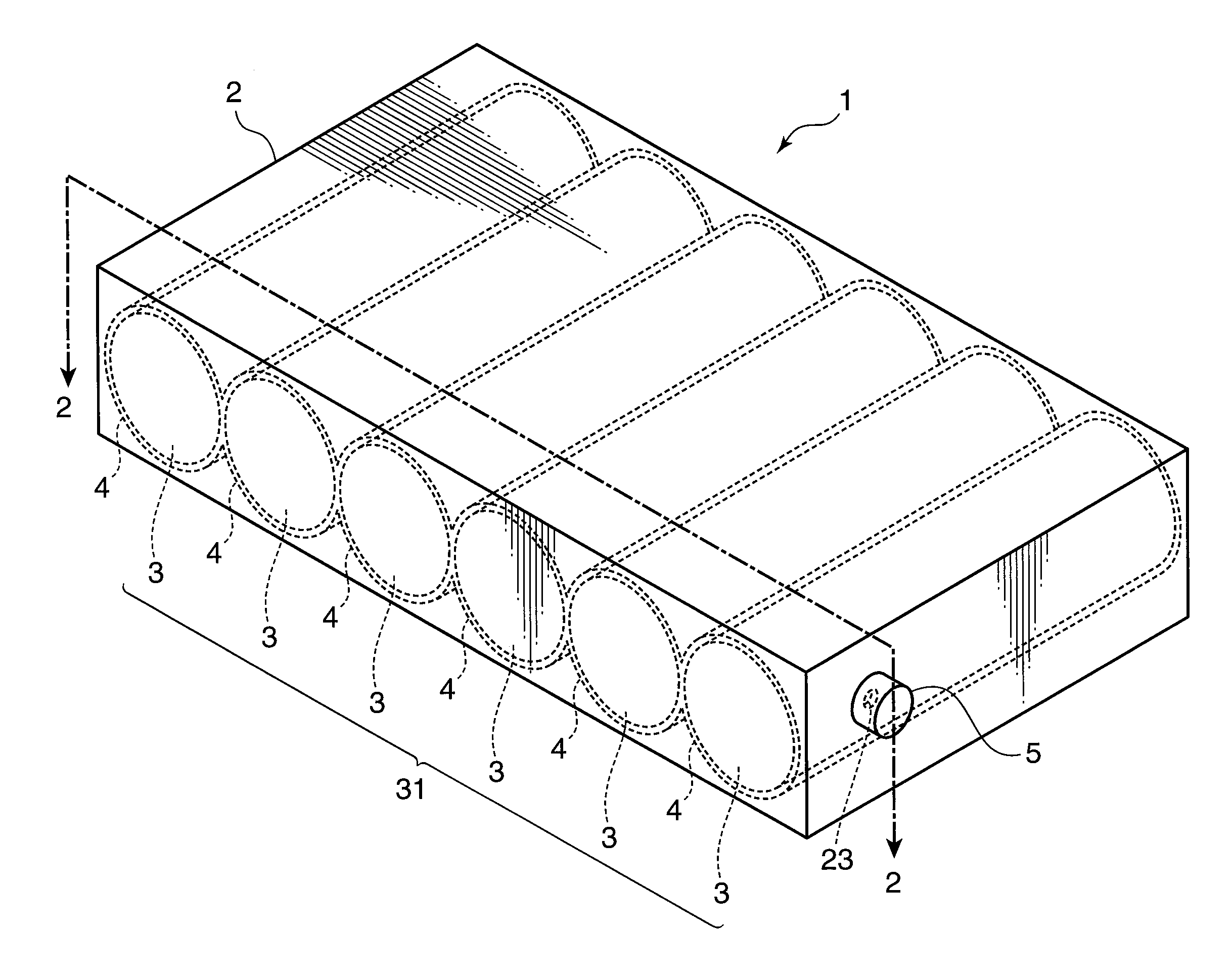
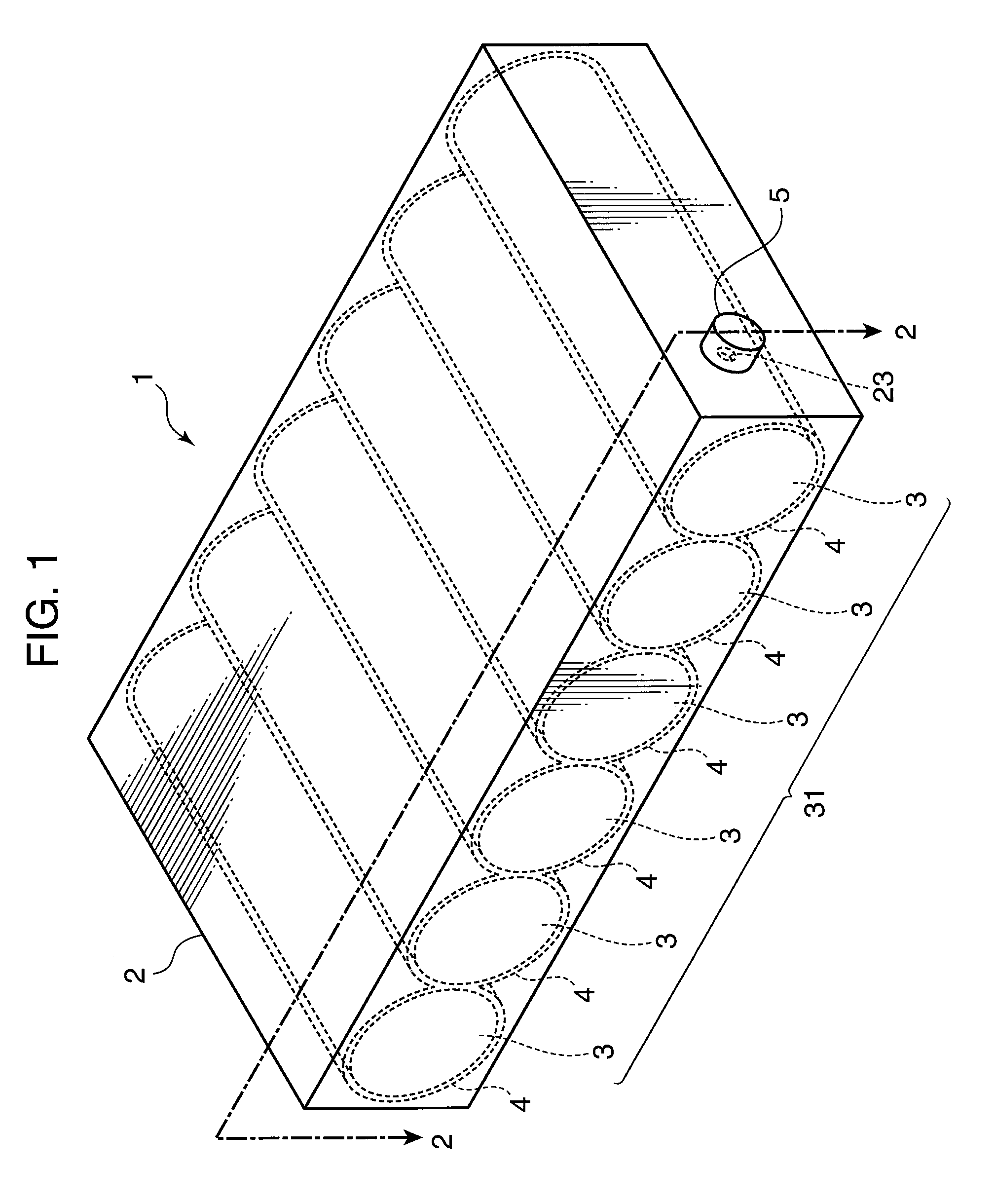
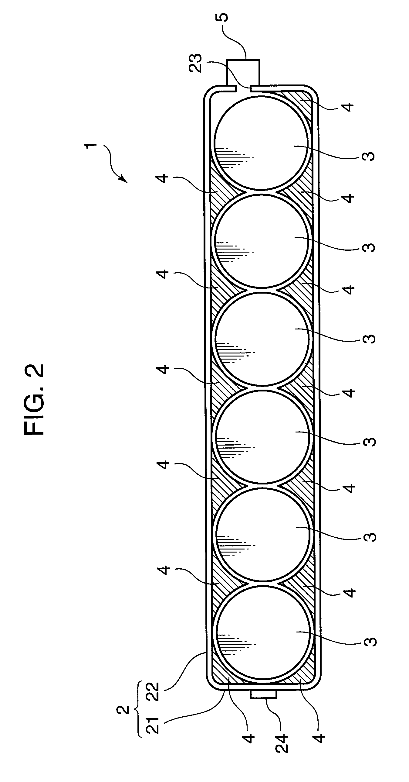
[0070]As are shown in FIG. 1 and FIG. 2, the batteries 3 are aligned in the case 2 with no space between and the protrusion-like filling members 4 were provided to the battery accommodation portion 21 and the battery pack lid 22 so as to reduce a space between the batteries 3 and the inner wall of the case 2. The pack internal, spatial volume of the case 2 in this instance was 15 cc. Herein, the pressure valve 5 was not used so that the opening 23 was exposed to the outside.

Example

Example 2

[0071]A battery pack of Example 2 was fabricated by aligning the batteries 3 while leaving an interval t of 5 mm from one battery 3 to another battery 3 as are shown in FIG. 6A and FIG. 6B and using stainless plates as the filling members 4 disposed between the respective batteries 3. Herein, the pressure valve 5 was not used so that the opening 23 was exposed to the outside.


PUM


Abstract

A battery pack includes a battery having a risk of releasing a gas under abnormal conditions, a case that accommodates the battery, and an oxygen reducing portion that reduces an amount of oxygen within the case.

Description

FIELD OF THE INVENTION[0001]The present invention relates to a battery pack accommodating a battery having a risk of releasing a gas under abnormal conditions and to a battery-mounted device.DESCRIPTION OF THE RELATED ART[0002]Recently, in association with diversification of electronic devices, a need for high-capacity, high-voltage, high-power, and safer battery and battery pack is increasing. In order to provide a battery and a battery pack with particularly high safety, there has been known a technique for providing a battery and a battery pack with various types of protection means, such as a PTC (Positive Temperature Coefficient) or a temperature fuse to prevent a temperature rise, and further a protection circuit to interrupt a current by sensing an internal pressure of the battery. A technique for providing a battery pack with a control circuit that controls charge and discharge of a battery for preventing the battery from being placed under abnormal conditions has been also ...

Claims


Application Information

Patent Timeline
IPC IPC(8): H01M2/12H01M10/34H01M50/213H01M50/229H01M50/231H01M50/28H01M50/282H01M50/289H01M50/35
CPCH01M2/105H01M2/1061H01M2/1072H01M2/1094H01M2/12H01M2/1252Y02T10/7011H01M2/16H01M10/0525H01M10/52H01M2200/10H01M2200/20H01M2/127Y02E60/10H01M50/213H01M50/30H01M50/383H01M50/394H01M50/24H01M50/35H01M50/229H01M50/282H01M50/231H01M50/28H01M50/289
Inventor HIRAKAWA, YASUSHINISHINO, HAJIMETAKAMURA, KOSHI
Owner PANASONIC CORP
Why Eureka
Try Eureka