Robotic cleaning head

a cleaning head and robot technology, applied in the field of robotic cleaning heads, can solve problems such as adversely affecting the steering accuracy, and achieve the effect of less sensitive manoeuvr

Inactive Publication Date: 2010-03-04
KONINKLIJKE PHILIPS ELECTRONICS NV
View PDF1 Cites 14 Cited by
  • Summary
  • Abstract
  • Description
  • Claims
  • Application Information

AI Technical Summary

Benefits of technology

[0004]It is an object of the invention to provide a cleaning head of which the maneuvera

Problems solved by technology

Such a reduction of the contact pressure between the drive system and the floor on one side of the drive system allow

Method used


Image

  • Robotic cleaning head
  • Robotic cleaning head
  • Robotic cleaning head

Examples


Embodiment Construction

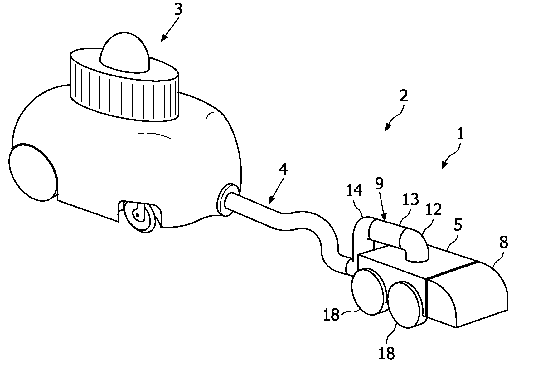
[0019]In FIG. 1, an autonomous vacuum cleaning system 2 composed of a canister unit 3, a robotic cleaning head 1 and a hose assembly 4 interconnecting the canister unit 3 and the robotic cleaning head 1 is shown.

[0020]According to the present example, the canister unit 3 is self-propelled and self-steering and includes a drive system, a canister, a power supply and an electric fan for generating suction power. The drive system of the canister unit 3 has two driven wheels located at the back corners (only one is visible in the figure) and two castors located near the hose connection at the front of the canister unit (only one is visible in the figure).

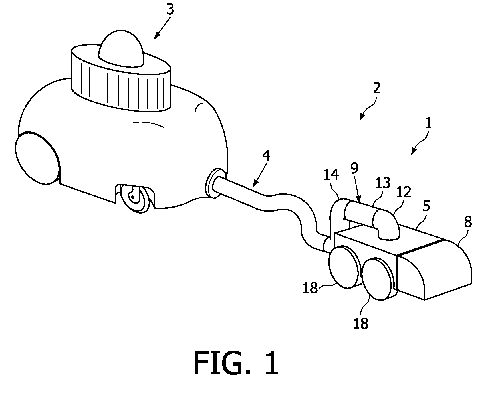
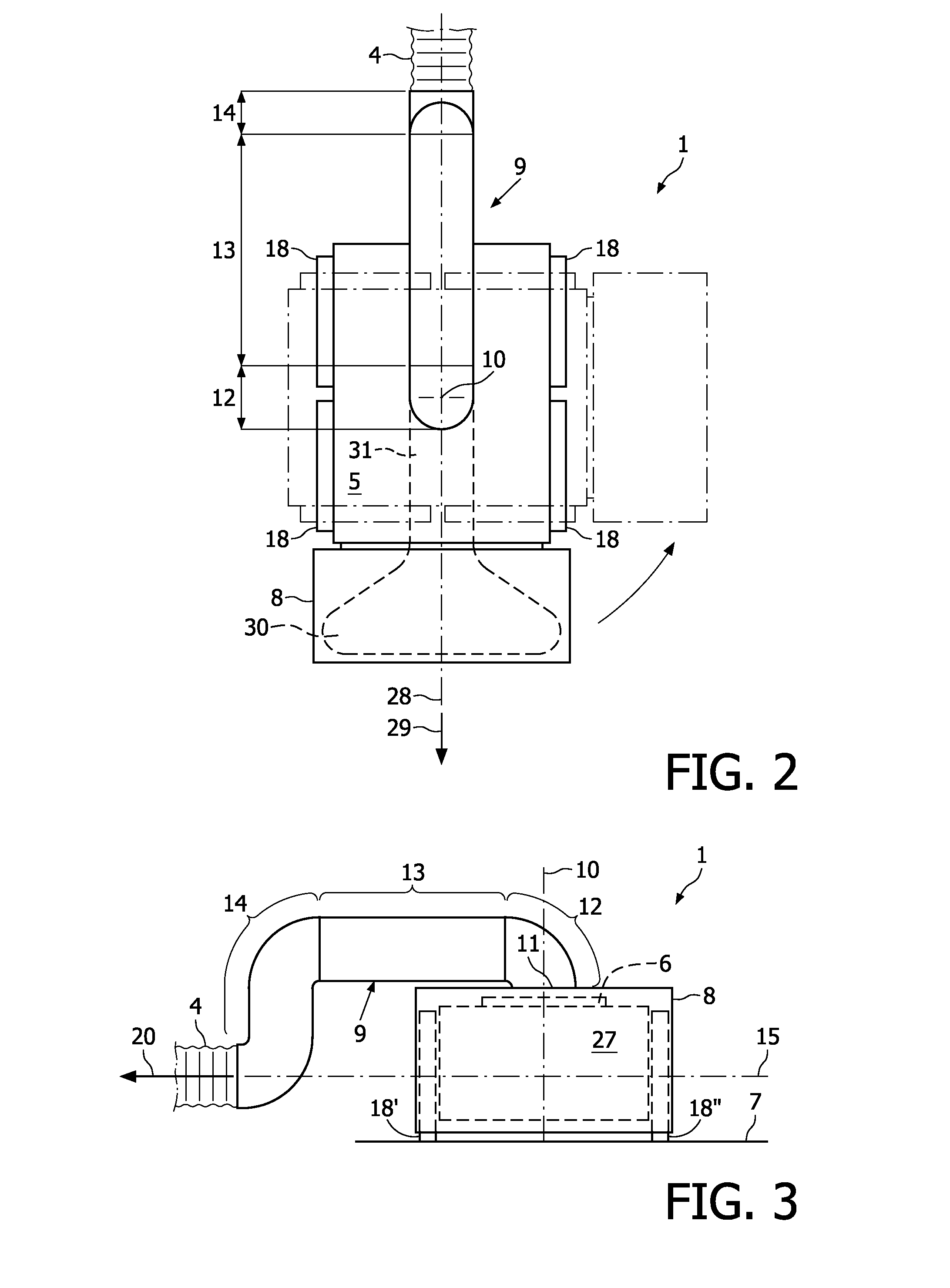
[0021]The cleaning head 1 (shown in more detail in FIGS. 2 and 3) is also self-propelled and self-steering by means of a drive system including a control system 6, a drive assembly 27 and wheels 18. The vacuum hose assembly 4 communicates with a cleaning nozzle 8 of the cleaning head 1 so that the vacuum generated by the canister unit i...


PUM


Abstract

A robotic cleaning head (1; 101) for use as part of an autonomous vacuum cleaning system (2) including a canister unit (3) and a hose assembly (4; 104) connecting the cleaning head (1; 101) to the canister unit (3). The cleaning head (3) has a chassis (5; 105), a drive system (6; 18; 27), a vacuum cleaning nozzle (8; 108) and a conduit (9; 109). The conduit (9; 109) communicates with an air passage bound by the cleaning nozzle (8; 108). It is suspended pivotable about a pivot axis (10; 110) and includes an inlet (11; 111) provided on top of said chassis (5; 105), and an elbow section (12; 112) downstream of the inlet (11; 111), and the conduit (9; 109) is suspended and shaped such that a line of action (15; 115) of a tension force (20; 120) exerted by the hose assembly (4; 104) onto the chassis (5; 105), via the conduit (9; 109) to which the hose assembly (4; 104) is connected, extends spaced below a downstream end of the elbow section (12; 112).

Description

FIELD OF THE INVENTION[0001]The invention relates to a robotic cleaning head for use as part of an autonomous vacuum cleaning system further including a canister unit and a hose assembly connecting the cleaning head to the canister unit.BACKGROUND OF THE INVENTION[0002]Such a robotic cleaning head is disclosed in European patent application 1 360 922. The canister unit holds a fan, a motor for driving the fan, dust filters and a dust collection chamber. Thus, the cleaning head can have relatively small dimensions, which is advantageous for agility and for reaching encumbered areas, for example, under furniture and in corners. For the maneuverability of the cleaning head, it is advantageous that the hose connects to a conduit of the cleaning head which is pivotable about a pivot axis and that the conduit includes an elbow section downstream of an inlet of the conduit extending coaxially with the pivot axis.[0003]In operation, the hose assembly exerts forces on both the cleaning head ...

Claims


Application Information

Patent Timeline
IPC IPC(8): A47L5/00
CPCA47L5/36A47L2201/00A47L9/24
Inventor SPLINTER, ALEXANDER POUL
Owner KONINKLIJKE PHILIPS ELECTRONICS NV
Why Eureka
Try Eureka