Automatically adjustable power jaw

a technology of automatic adjustment and power jaw, which is applied in the direction of wrenches, drilling casings, drilling pipes, etc., can solve the problems of increasing the risk of injury by operator contact with the wrench assembly, and increasing the operational time, so as to increase the operational time and high torque

Inactive Publication Date: 2010-03-04
HAWK INDS A CALIFORNIA CORP
View PDF9 Cites 14 Cited by
  • Summary
  • Abstract
  • Description
  • Claims
  • Application Information

AI Technical Summary

Benefits of technology

[0010]To make-up or break out a drill pipe connection, high torque must be supplied over a large angle which is supplied through energizing the jaws. The jaws are initially energized by providing fluid-operated grip cylinders that pivot the hook and head relative to one another, closing and thereby tighten the grip the jaw has on the pipes. The initial engagement of the pipe by the grip cylinders commences the torquing, which allows subsequent torquing to be more effective. Other fluid-operated means, such as a hydraulic torque cylinder, are then provided to effect the torquing.
[0011]As explained above, while the prior art jaws include automated mechanisms for gripping the pipe and for applying high torque to the jaws, the prior art jaws still require manual adjustment of the wrenches to allow for the receipt of pipes of varying diameter. As such, to commence the making and breaking process, each jaw has to be manually opened and closed to allow the wrenches to receive pipes of varying diameter. Requiring manually operation of the jaws increases the operational time associated with the make-up and break out process and also increase the risk of injury by operator contact with the wrench assembly.
[0012]A need therefore exists for an improved jaw and jaw assemblies that reduce the time it takes to make-up or break out a tubular connection. A further need exists for increasing safety of operation of the jaws by minimizing operator contact.
[0013]An improved jaw apparatus for making or breaking a tubular connection is provided that is capable of receiving pipes of various diameters through an automated means. In one example of an implementation of the invention, a jaw is providing having a head adapted to receive a hook having a threaded shank end. The threaded shank end is engaged at the head end opposite the hook end by a powered nut adjustment assembly. The adjustment assembly may be operated by a control unit to allow for the automatic opening and closing of the jaw for receiving pipes of varying diameters. When utilizing more than one jaw, such as in a wrench (or jaw) assembly, all the jaws in the assembly may be simultaneously or sequentially controlled to open and close the jaws on the pipe joints for making and breaking the joints. Simultaneous automated control of the opening and closing of the jaws provides for reduced make-up and break-up time, as well as increased safety features.

Problems solved by technology

Requiring manually operation of the jaws increases the operational time associated with the make-up and break out process and also increase the risk of injury by operator contact with the wrench assembly.

Method used


Image

  • Automatically adjustable power jaw
  • Automatically adjustable power jaw
  • Automatically adjustable power jaw

Examples


Embodiment Construction

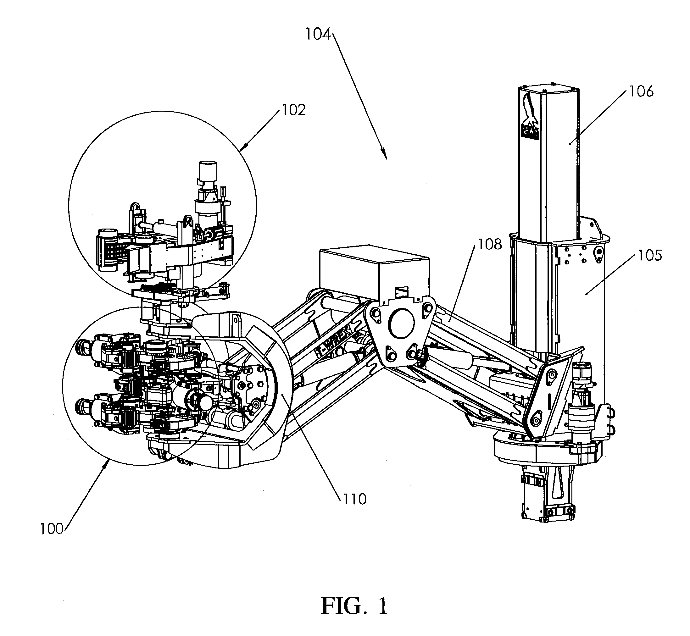
[0032]FIG. 1 illustrates a perspective view of one example of an implementation of an automatically adjustable wrench assembly 100 and a self-adjusting pipe spinner 102 mounted on a pedestal assembly 104. As illustrated, the pedestal assembly 104 is made up of a strong support column 106 having an extension arm 108. A C-head 110 (or mounting unit) is mounted on the end of the extension arm 108 opposite the column 106 for supporting and suspending the pipe spinner 102 and wrench assembly 100 over the wellhead of an oil well.

[0033]Fitted on the column 106 of the pedestal assembly 104 is a trolley 105. Through the use of hydraulic motors and cylinders, the trolley 105 is able to pivot the extension arm 108 about the column 106 in a horizontal direction and move the extension arm 108 up and down the column 106 in the vertical direction. The extension arm 108, also through the use of hydraulic cylinders, is able to travel longitudinally to extend or retract the position of the C-head 110...


PUM


Abstract

An improved jaw apparatus is provided for making or breaking a tubular pipe connection. The jaw includes a head adapted to receive a hook having a threaded shank end. The threaded shank end is engaged at the head end opposite the hook end by a hydraulic powered nut adjustment assembly. The adjustment assembly may be operated by a control unit to allow for the automatic opening and closing of the jaw for receiving pipes of varying diameters.

Description

BACKGROUND OF THE INVENTION[0001]1. Field of the Invention[0002]The present invention generally relates to equipment used in the maintenance and servicing of oil and gas production wells, and more particularly, relates to power jaws or wrenches of the type used in conjunction with making or breaking threaded joints between successive tubing elements that make-up the continuous tubing string extending through a well bore into the underground deposits.[0003]2. Related Art[0004]In the construction of oil or gas wells, it is usually necessary to construct long drill pipes. Due to the length of these pipes, sections of pipe are progressively added to the pipe string as it is lowered into the well from a drilling platform. It is common practice to use wrench assemblies to apply a predetermined torque to make-up or break out the drill pipe connections. The wrench assemblies are typically located on a platform, either on rails or hung from a derrick on a chain. Examples of prior art wrench ...

Claims


Application Information

Patent Timeline
Patent Type & Authority Applications(United States)
IPC IPC(8): B25B13/50B25B13/12B25B13/14
CPCE21B19/165E21B19/164
Inventor HAUK, THOMAS D.JORDA, ANTHONY B.PEREZ, RAUL H.RIVERA, MICHAEL ERNEST
Owner HAWK INDS A CALIFORNIA CORP
Why Eureka
Try Eureka