
Method for enhancing fretting fatigue resistance of alloys

a technology of alloys and fretting fatigue, applied in the direction of metallic material coating process, solid-state diffusion coating, coating, etc., can solve the problems of increasing the alloy's fretting fatigue resistance, shortening the useful life of the prosthesis, and washed away the ablated surface material, so as to reduce the size of the orthopedic component, reduce the cost, and improve the effect of the design of the orthopedic componen

Inactive Publication Date: 2010-03-04
ZIMMER INC
View PDF8 Cites 31 Cited by
  • Summary
  • Abstract
  • Description
  • Claims
  • Application Information

AI Technical Summary

Benefits of technology

[0008]The present invention provides a method for increasing the fretting fatigue resistance of an alloy by prehardening a surface of the alloy followed by laser shock peening the prehardened surface. In one exemplary embodiment, an orthopedic prosthesis is formed from a titanium alloy and subjected to surface nitriding followed by laser shock peening. By nitriding the titanium alloy, the hardness of the alloy is increased to a depth of as much as 0.02 μm below the surface. Then, by subjecting the nitrided surface of the alloy to laser shock peening, the fretting fatigue of the surface may be increased by more than 100%.
[0011]Advantageously, improving by 100% or more the fretting fatigue resistance of the surface of an orthopedic implant allows the orthopedic implant to withstand loads in excess of twice of the anticipated loading requirements during use, which are typically three times the patient's body weight. As a result, the size of the orthopedic component may be decreased. Additionally, the design of the orthopedic components may also be altered, as less material may be needed in certain positions to bear the same loads as traditional implants. Furthermore, by laser shock peening a previously hardened, e.g., nitrided, surface, only selected sections of a prosthesis, as opposed to the entirety of a prosthesis, may be subjected to the desired surface modification. As a result, the prosthesis may be produced for a substantially lower cost than a prosthesis that is laser shock peened in its entirety.
[0012]In one form thereof, the present invention provides a method of enhancing the fretting fatigue resistance of an alloy, including the steps of: forming an orthopedic component from an alloy, wherein the alloy has a melting point; nitriding at least a portion of the orthopedic component to form a nitrided surface, the nitrided surface having a first fretting fatigue strength; and laser shock peening at least a portion of the nitrided surface of the orthopedic component to form a laser shock peened surface, wherein the laser shock peened surface has a second fretting fatigue strength.
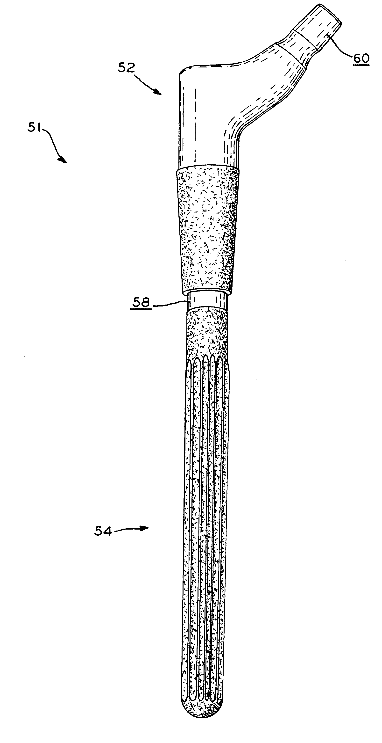
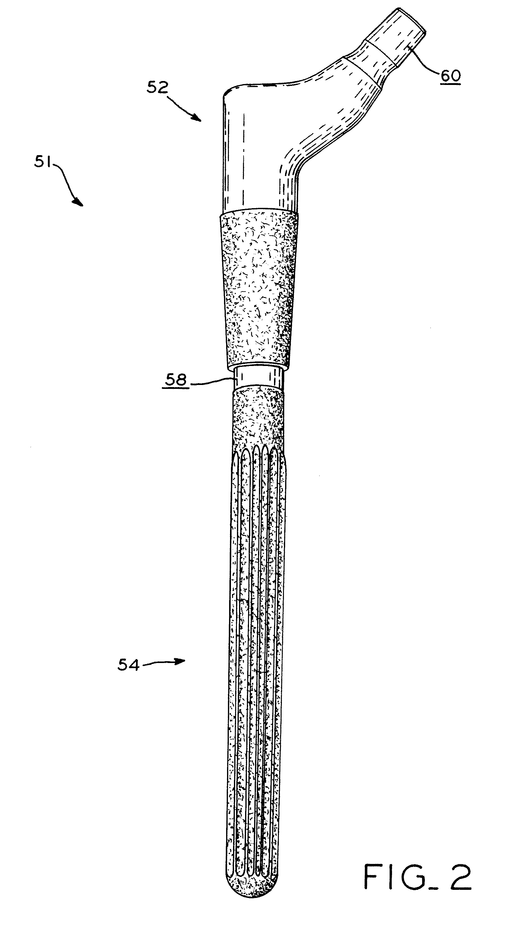
[0013]In another form thereof, the present invention provides a method of enhancing the fretting fatigue resistance of an alloy, including the steps of: forming a modular orthopedic component from an alloy having a melting point, the modular orthopedic component including: a first component defining a male tapered surface; and a second component defining a female tapered surface, the male tapered surface of the first component configured to form a taper lock with the female tapered surface of the second component; nitriding at least one of the male tapered surface of the first component and the female tapered surface of the second component to form a nitrided surface, the nitrided surface having a first fretting fatigue; and laser shock peening at least a portion of the nitrided surface to form a laser shock peened surface, wherein the laser shock peened surface has a second fretting fatigued strength.

Problems solved by technology

As a result, fretting fatigue may occur within the titanium alloy which can shorten the useful life of the prosthesis.
This transformation results in the generation of shockwaves that are directed toward the alloy's surface by the curtain of flowing water, which also washes away the ablated surface material.
Moreover, the increase in the alloy's resistance to fretting fatigue cannot be directly correlated to the increase in the hardness of the nitrided alloy after laser shock peening, as it is only improved by approximately 50% as compared to the nitrided alloy.

Method used


Image

  • Method for enhancing fretting fatigue resistance of alloys
  • Method for enhancing fretting fatigue resistance of alloys
  • Method for enhancing fretting fatigue resistance of alloys

Examples


example

[0030]The following non-limiting Example illustrates various features and characteristics of the present invention, which is not to be construed as limited thereto. The following abbreviations are used throughout the Example unless otherwise indicated.

TABLE 1AbbreviationsAbbreviationFull WordFFahrenheit°degreeHzHertzNNewtonKHN10 gKnoop HardnessGWgigawattcmcentimeterNdNeodymiumTiTitaniumAlAluminumVVanadiumkbarkilobar

Fretting Fatigue Tests of Modular Components with Improved Surface

[0031]Wrought mill annealed Ti-6Al-4V ELI titanium alloy (ASTM F-136-02A) bar stock was obtained from Supra Alloys, Inc., of Camarillo, Calif. The alloy bar stock was formed into ten complete, modular hip stems each having a mid-stem Morse taper. The modular hip stems that were formed were similar to hip stems available in the ZMR® Hip System, commercially available from Zimmer, Inc., of Warsaw, Ind. “ZMR” is a registered trademark of Zimmer, Inc., of Warsaw, Ind. Each of the modular components that form th...


PUM

PropertyMeasurementUnit
temperatureaaaaaaaaaa

Abstract

A method for increasing the fretting fatigue resistance of an alloy by prehardened a surface of the alloy followed by laser shock peening the prehardened surface. In one exemplary embodiment, an orthopedic prosthesis is formed from a titanium alloy and subjected to surface nitriding followed by laser shock peening. By nitriding the titanium alloy, the hardness of the alloy's surface is increased. Then, by subjecting the nitrided surface of the alloy to laser shock peening, the fretting fatigue of the nitrided surface may be increased by more than 100%.

Description

CROSS-REFERENCE TO RELATED APPLICATIONS[0001]This application claims the benefit under Title 35 U.S.C. §119(e) of U.S. Provisional Patent Application Ser. No. 61 / 093,595, entitled METHOD FOR ENHANCING FRETTING FATIGUE RESISTANCE OF ALLOYS, filed on Sep. 2, 2008, the entire disclosure of which is expressly incorporated by reference herein.BACKGROUND[0002]1. Field of the Invention[0003]The present invention relates to methods for enhancing the fretting fatigue resistance of alloys and, particularly, methods of enhancing the fretting fatigue of alloys by the laser shock peening of prehardened surfaces.[0004]2. Description of the Related Art[0005]Orthopedic prostheses are used to replace and / or repair damaged or diseased bone in a patient's body. To construct an orthopedic prosthesis, titanium alloys, such as Ti-6Al-4V, may be used which incorporate the superior strength to weight ratio of titanium. Additionally, some prostheses are manufactured to be modular, i.e., a number of smaller ...

Claims


Application Information

Patent Timeline
Patent Type & Authority Applications(United States)
IPC IPC(8): C23C8/24C22F1/00C22F1/18
CPCC21D1/78C21D10/005C23C8/80C23C8/24C23C8/36C22F1/10
Inventor BHAMBRI, SUSHIL K.
Owner ZIMMER INC
Learn More