Heat dissipation apparatus incorporating a fan

a technology of heat dissipation apparatus and fan, which is applied in the direction of lighting and heating apparatus, basic electric elements, and semiconductor devices. it can solve the problems of complicating the assembly affecting the performance of the heat dissipation apparatus

Inactive Publication Date: 2010-03-04
FU ZHUN PRECISION IND SHENZHEN +1
View PDF17 Cites 8 Cited by
  • Summary
  • Abstract
  • Description
  • Claims
  • Application Information

AI Technical Summary

Benefits of technology

[0007]However, in the heat dissipation apparatus, the fan is assembled to the heat sink via the plurality of screws, which complicates the assembly of the heat dissipation apparatus.

Problems solved by technology

It is well known that if heat generated by electronic components, such as integrated circuit chips, during operation is not efficiently dissipated, these electronic components may suffer damage.
However, in the heat dissipation apparatus, the fan is assembled to the heat sink via the plurality of screws, which complicates the assembly of the heat dissipation apparatus.

Method used


Image

  • Heat dissipation apparatus incorporating a fan
  • Heat dissipation apparatus incorporating a fan
  • Heat dissipation apparatus incorporating a fan

Examples


Embodiment Construction

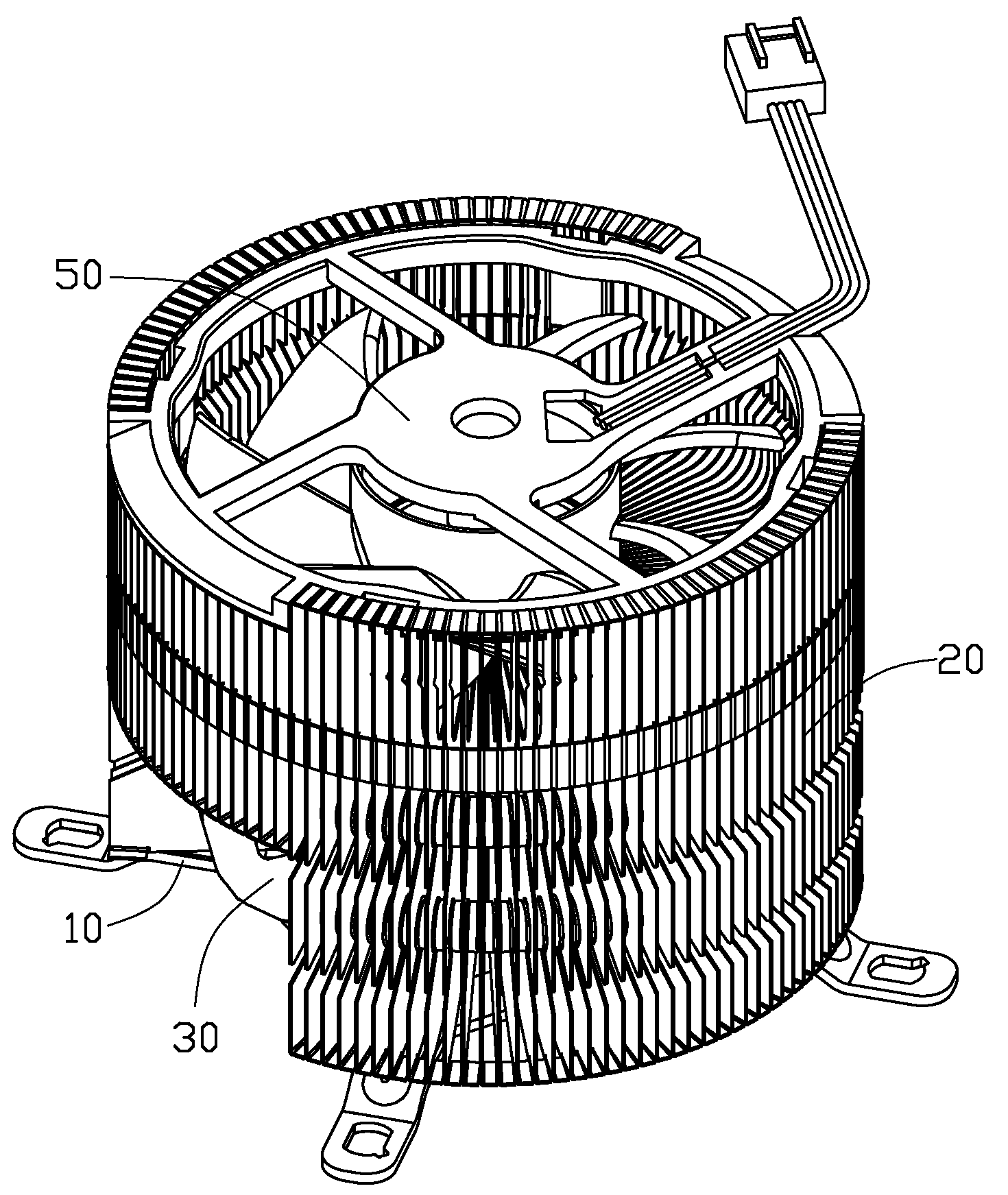
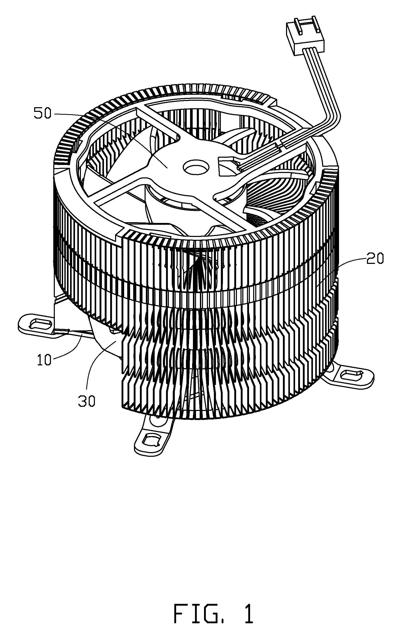
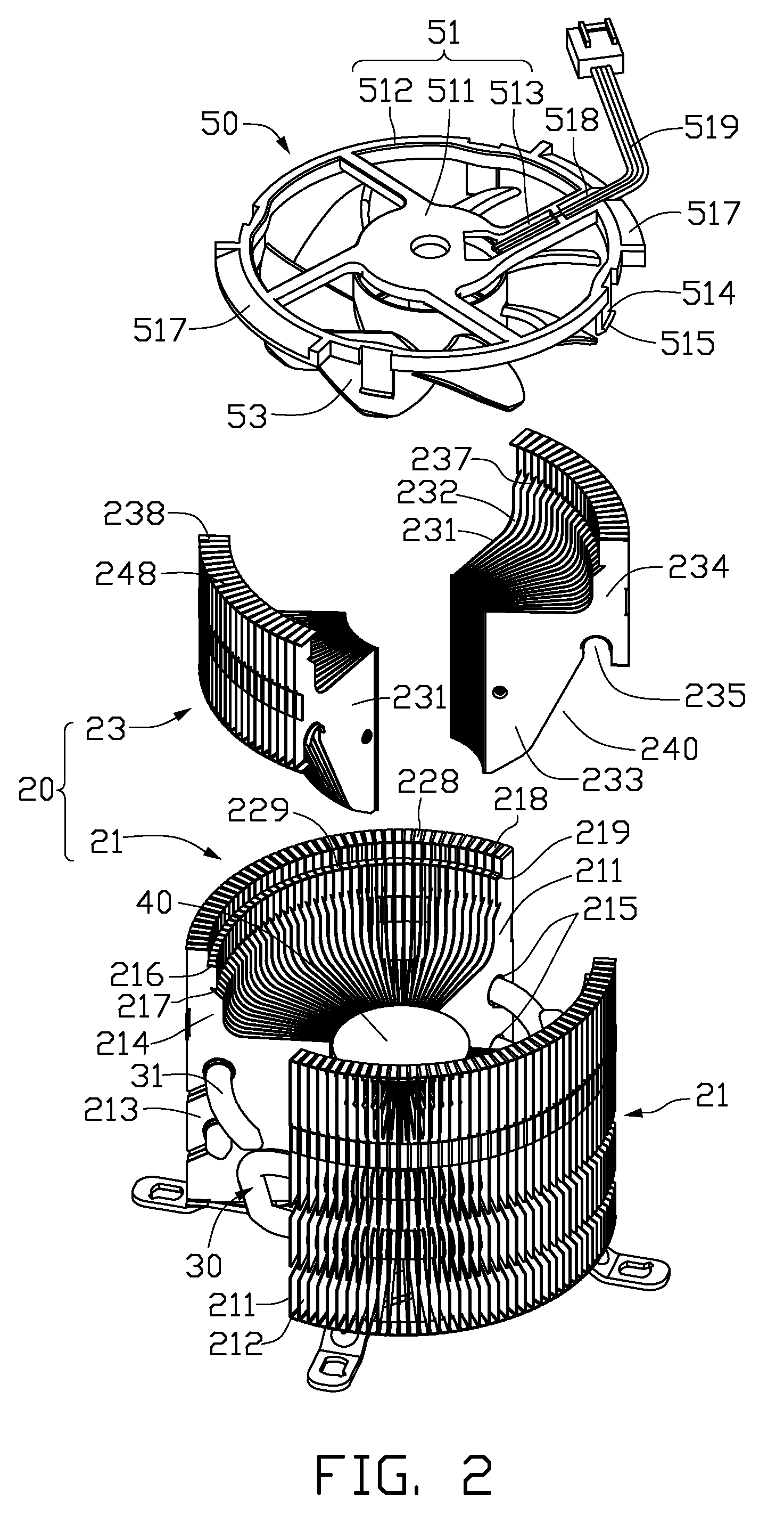
[0013]Referring to FIGS. 1 and 2, a heat dissipation apparatus in accordance with one embodiment of the disclosure is shown. The heat dissipation apparatus includes a high heat conductive base 10, a heat sink 20, a plurality of heat pipes 30 thermally connecting the base 10 with the heat sink 20, a heat conductive core 40 received in the heat sink 20, and a fan 50 mounted in a top of the heat sink 20.

[0014]The heat sink 20 is annular, and includes a pair of first fin assemblies 21 and a pair of second fin assemblies 23.

[0015]Each of the first fin assemblies 21 is sectorial, and includes a plurality of radial first fins 211 stacked along a circumferential direction of the heat sink 20. An air channel 212 is defined between every two adjacent first fins 211.

[0016]Each of the first fins 211 includes a rectangular main body 213 and an extension arm 214 extending upwardly from the main body 213. Each of the first fin assemblies 21 defines a plurality of arcuate first receiving grooves 21...


PUM


Abstract

A heat dissipation apparatus includes a heat sink and a fan. The heat sink includes a plurality of radial first and second fins. The first and second fins each include a main body and an extension arm extending upwardly from the main body. The main bodies and the extension arms cooperatively form a space therebetween for securely receiving the fan therein. Each extension arm defines an engaging groove communicating with the space. A height of the extension arm of each second fin is less than that of the extension arm of each first fin. A fixing recess is defined over the extension arms of the second fins. The fan includes a frame extending downwardly out a plurality of legs and radially out a fixing arm. The legs have hooks engaging in the engaging grooves, and the fixing arm is fixed in the fixing recess.

Description

CROSS-REFERENCE TO RELATED APPLICATION[0001]Relevant subject matter is disclosed in co-pending U.S. patent application Ser. No. 12 / 331,391, filed on Dec. 9, 2008, both of which are assigned to the same assignee as the present application. The disclosure of the co-pending application is incorporated herein by reference.BACKGROUND[0002]1. Technical Field[0003]The present disclosure generally relates to heat dissipation, and particularly to a heat dissipation apparatus utilizing a fan for enhancing a dissipating efficiency.[0004]2. Description of Related Art[0005]It is well known that if heat generated by electronic components, such as integrated circuit chips, during operation is not efficiently dissipated, these electronic components may suffer damage. Thus, heat dissipation apparatuses are often used to cool the electronic components.[0006]A typical heat dissipation apparatus includes a heat sink and a fan. The heat sink is thermally connected with a heat generating electronic compo...

Claims


Application Information

Patent Timeline
Patent Type & Authority Applications(United States)
IPC IPC(8): F28F13/00F28D21/00F28D15/02
CPCH01L23/3672H01L23/427H01L23/467H01L2924/0002H01L2924/00
Inventor ZHAO, DI-QIONGDENG, HONG-BO
Owner FU ZHUN PRECISION IND SHENZHEN
Why Eureka
Try Eureka