System, method, and apparatus for throat corner scoop offtake for mixed compression inlets on aircraft engines

Active Publication Date: 2010-03-04
LOCKHEED MARTIN CORP
View PDF28 Cites 11 Cited by
  • Summary
  • Abstract
  • Description
  • Claims
  • Application Information

AI Technical Summary

Benefits of technology

[0009]Mixed compression inlets traditionally have been designed as axi-symmetric or two-dimensional configurations. Such designs typically include a throat bleed system that removes the low pressure boundary layer from the main duct via a shock trap or bleed holes and slots, which are designed to remove boundary layer and provide terminal shock stability. The throat corner scoops of the present invention are designed to do this for non-axi-symmetric mixed compression inlet configurations such as, for example, advanced diverterless streamline-traced inlets. In contrast to current and future architectures, the previous designs did not have acute corners and therefore did not need to address the issue of corner flow affecting engine operation. Thus, the present solution has the added advantage of enhancing the viability of advanced streamline traced mixed compression inlets.

Problems solved by technology

The low energy air captured in the shock trap 15 would likely be exhausted overboard as it typically does not have enough energy to be used as utility flow.
These exotic shapes impose additional geometric constraints that require novel approaches to bleed system design and integration.
Exotically-shaped, high speed engine inlets can suffer from several diverse performance losses.
First, mixed compression inlets with duct wall interfaces that form acute angles (such as streamline traced inlets) can develop vorticity and a thick boundary layer (e.g., corner flow) in these regions which can cause separation and flowfield distortion that reduces engine performance.
Second, a mixed compression inlet can undergo a process called “unstart” in which terminal shock stability is lost and airflow to the engine is drastically reduced, which consequently reduces engine performance.
Third, airflow from the engine inlet is required for nacelle ventilation, environmental control systems, and various other utility and subsystems.

Method used


Image

  • System, method, and apparatus for throat corner scoop offtake for mixed compression inlets on aircraft engines
  • System, method, and apparatus for throat corner scoop offtake for mixed compression inlets on aircraft engines
  • System, method, and apparatus for throat corner scoop offtake for mixed compression inlets on aircraft engines

Examples


Embodiment Construction

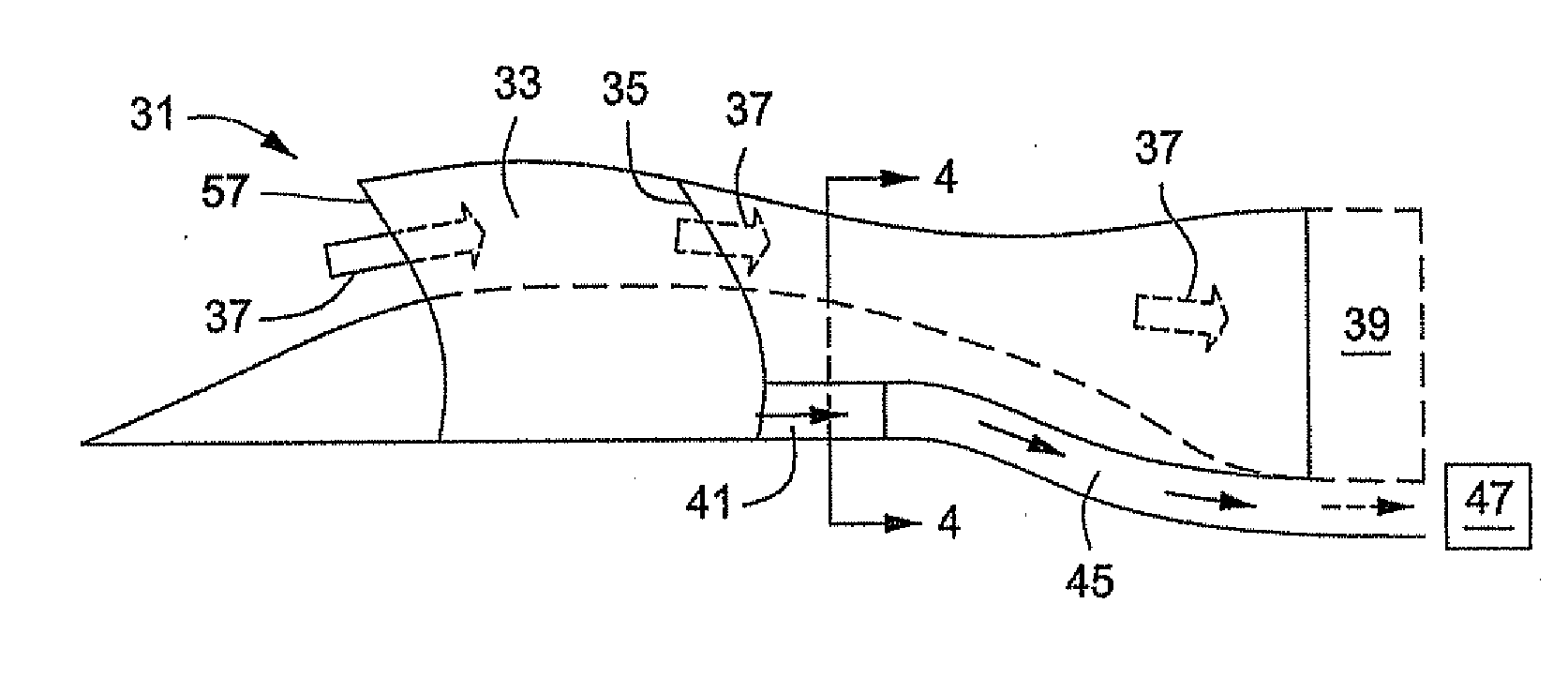
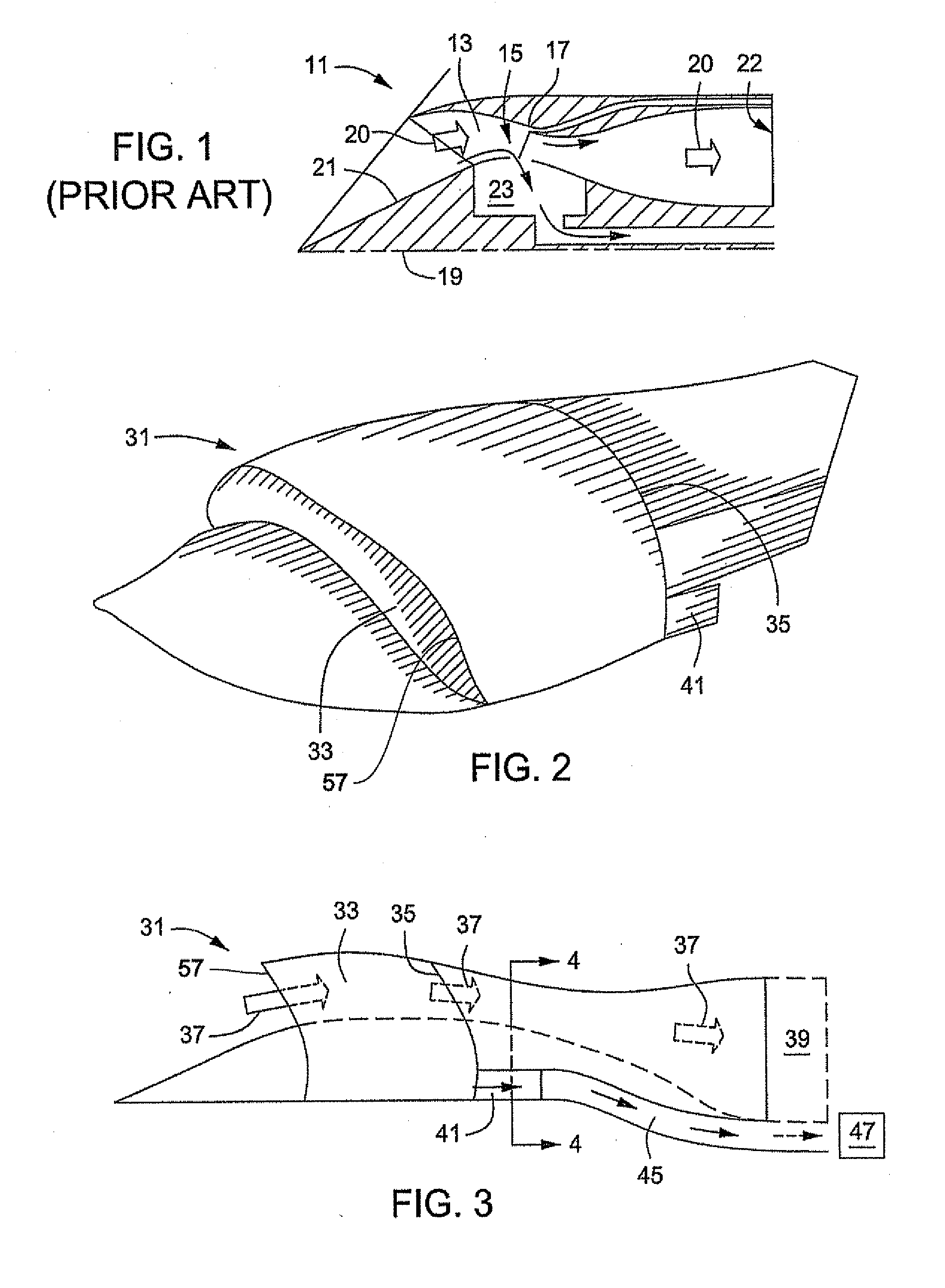
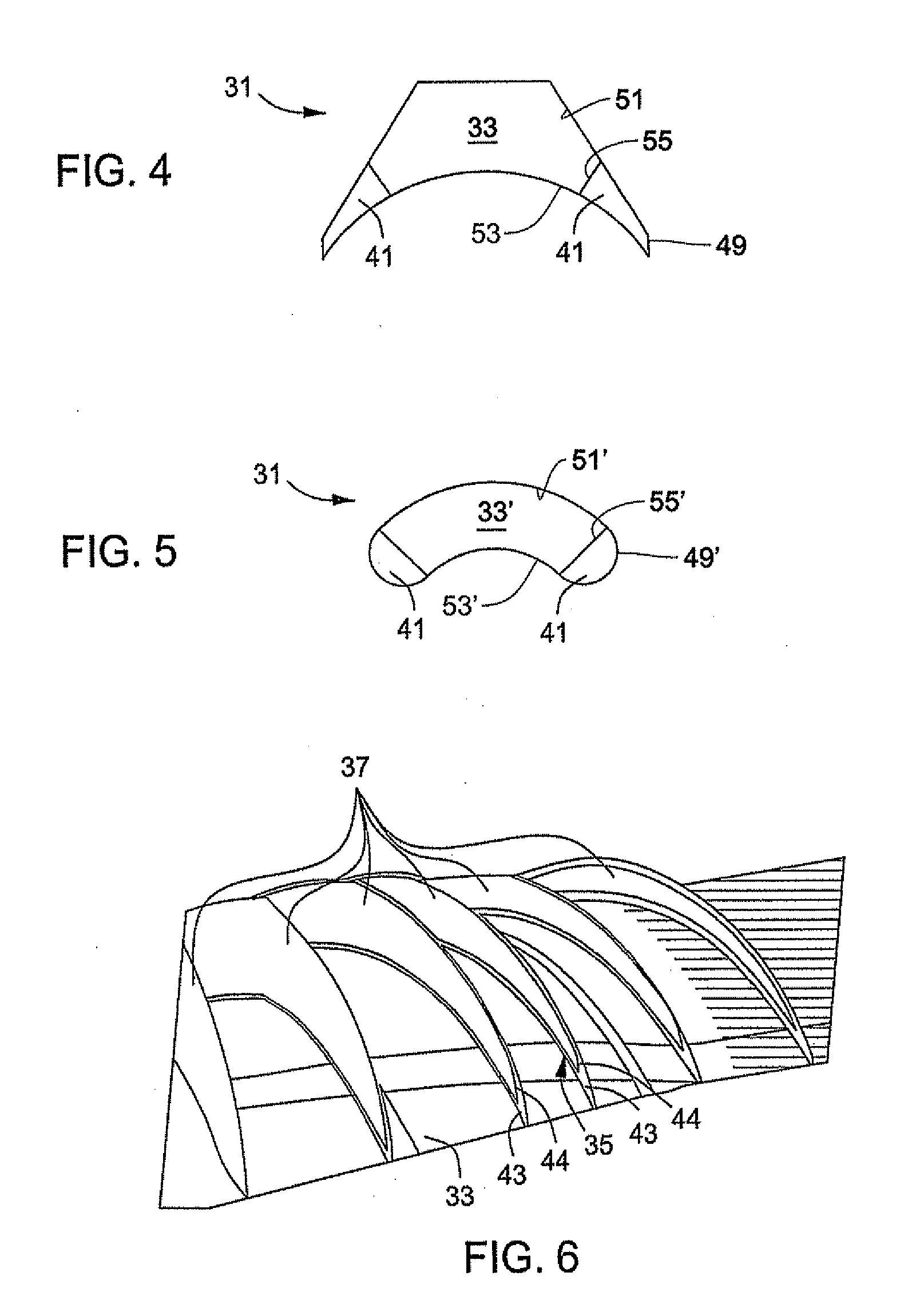
[0020]Referring to FIGS. 2-7, embodiments of a system, method and apparatus for manipulating airflow into a high speed aircraft engine is disclosed. As shown in FIGS. 2-4, one embodiment of the invention comprises a non-axi-symmetric, mixed compression inlet 31. The mixed compression inlet 31 comprises a forward supersonic diffuser 33, a minimum area throat region or throat 35, and a subsonic diffuser section downstream of the throat 35 to provide subsonic airflow to a high speed aircraft engine 39. The airflow 37 (FIG. 3) is captured by the inlet 31, compressed in the supersonic section 33 to the terminal normal shock just downstream of the throat 35, and is further decelerated in the subsonic diffuser to the desired Mach number at the engine 39. The engine 39 may be a single engine or may be bifurcated to feed multiple engines.

[0021]A small air intake or scoop 41 is located inside the mixed compression inlet 31. In one embodiment, the scoop 41 is a throat corner scoop 41 that prot...


PUM


Abstract

A system, method, and apparatus for throat corner scoop offtake for mixed compression inlets for high speed aircraft engine applications is disclosed. The throat corner scoops are small air intakes located inside the large mixed compression inlet. They are positioned in a region otherwise prone to generate low pressure airflow. The throat corner scoops capture and remove the low pressure airflow from the bulk stream that is passed on to the engine. This location also provides inlet stability enhancement, and the airflow is used on the auxiliary systems.

Description

BACKGROUND OF THE INVENTION[0001]1. Technical Field[0002]The present invention relates in general to inlet design for aircraft engines and, in particular, to an improved system, method, and apparatus for throat corner scoop offtake for mixed compression inlets for high speed aircraft engine applications.[0003]2. Description of the Related Art[0004]Air inlet systems for gas turbine powered supersonic aircraft are required to decelerate the approaching flow to subsonic conditions before it reaches the engine face. Supersonically, this can be done through shock waves or isentropic compression generated externally, internally, or by a mixture of both. Fixed geometry external compression inlets have typically been used for aircraft (e.g., the F-16 and F-18) designed for short excursions to supersonic conditions, due to the relative simplicity and light weight of these designs. Aircraft capable of higher speeds, such as the F-14 and F-15, have employed variable geometry external compressi...

Claims


Application Information

Patent Timeline
IPC IPC(8): B64D33/02
CPCB64D33/02B64D2033/026B64D2033/0226Y10T137/0536
Inventor LELAND, BRADLEY C.LUNDY, BRIAN F.KLINGE, JOHN D.
Owner LOCKHEED MARTIN CORP
Why Eureka
Try Eureka