Device for producing ring core, method for producing ring core and ring core produced by that method

a technology of ring core and ring core, which is applied in the direction of applying solid insulation, manufacturing stator/rotor bodies, and manufacturing tools, etc., can solve the problems of waste of scrap metal cut off from inside the ring sheet, and achieve the effect of increasing strength

Inactive Publication Date: 2010-03-04
HONDA MOTOR CO LTD
View PDF5 Cites 27 Cited by
  • Summary
  • Abstract
  • Description
  • Claims
  • Application Information

AI Technical Summary

Benefits of technology

[0024]With the above arrangement, the layers of the ring core comprise l

Problems solved by technology

Scrap metal cut off from ins

Method used


Image

  • Device for producing ring core, method for producing ring core and ring core produced by that method
  • Device for producing ring core, method for producing ring core and ring core produced by that method
  • Device for producing ring core, method for producing ring core and ring core produced by that method

Examples


first embodiment

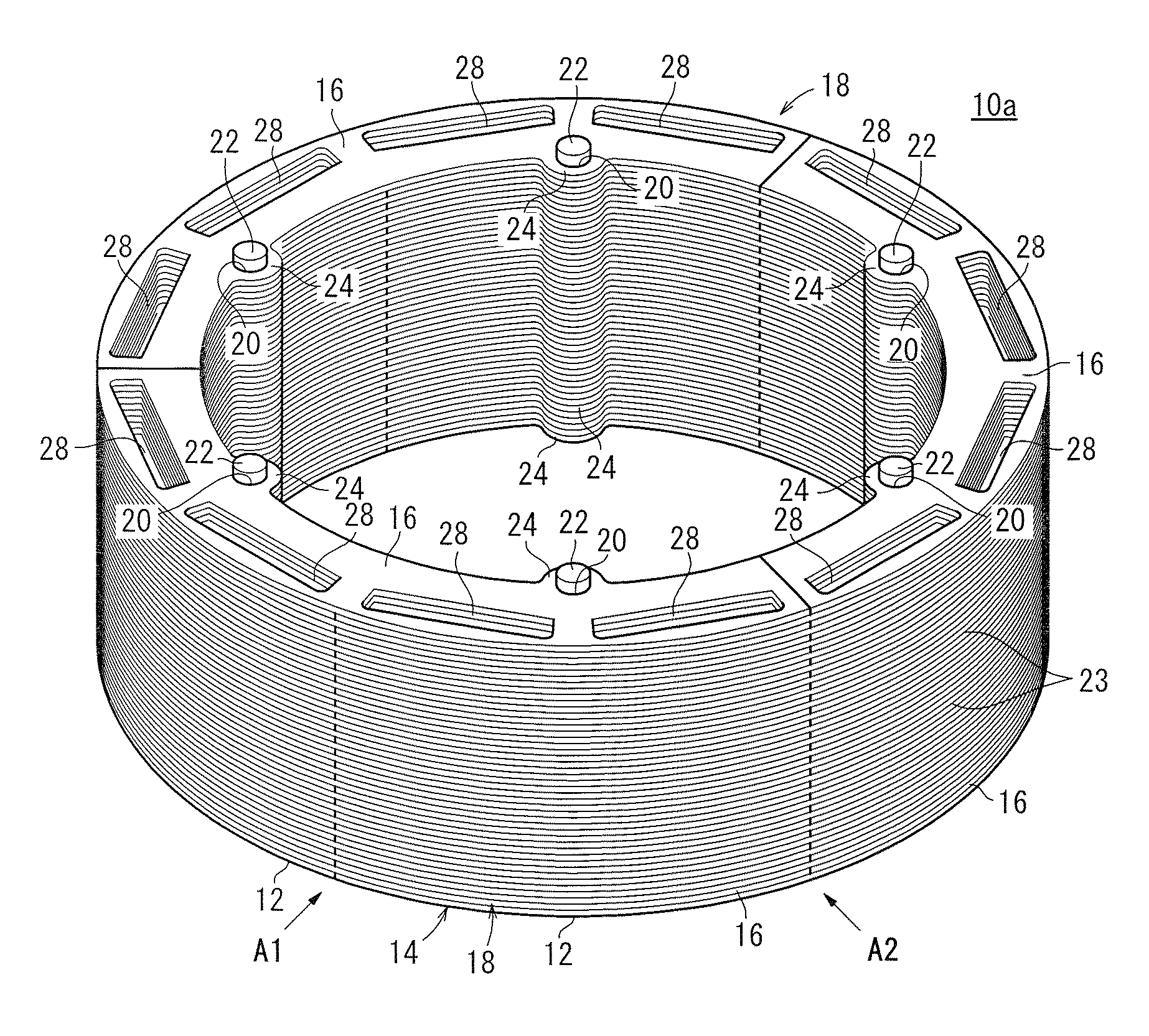
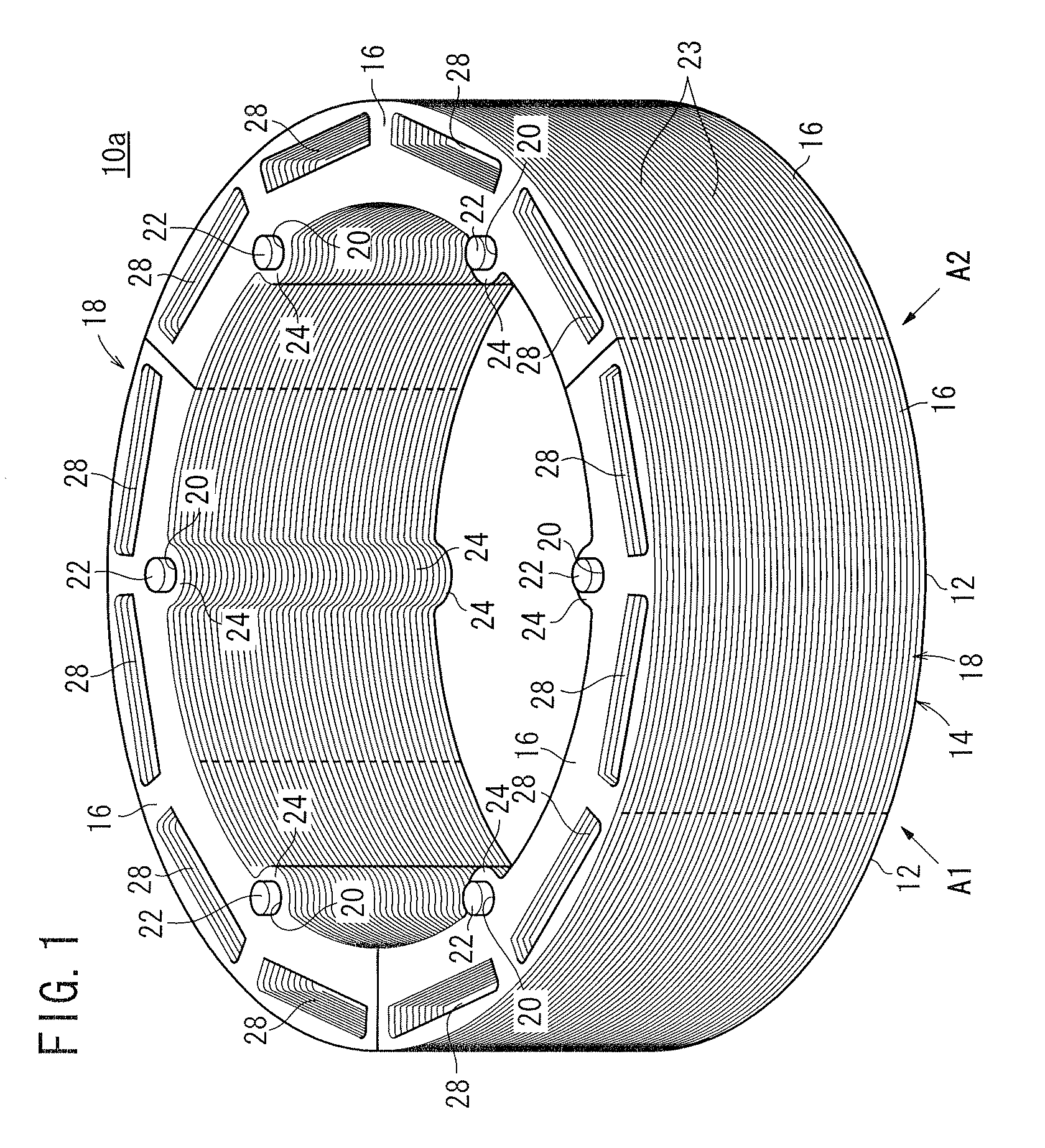
[0081]FIG. 1 is a perspective view of a rotor core (ring core) 10a manufactured by an apparatus for manufacturing a ring core according to the present invention. The rotor core 10a serves as part of a rotor, for example. The rotor and a stator, not shown, jointly make up an electric motor (rotary machinery).

[0082]The rotor core 10a comprises a ring-shaped first core plate 14 made up of a plurality of (three in the present embodiment) first separate core plates (rotor core pieces) 12 arranged circumferentially, each of the first separate core plates comprising a thin sectorial magnetic steel sheet, and ring-shaped second core plates 18 made up of second separate core plates (rotor core pieces) 16 arranged circumferentially, each of the second separate core plates comprising a thin sectorial magnetic steel sheet. The second core plates 18 are angularly spaced from the first core plate 14 by a predetermined phase. The rotor core 10a includes a total of fifty layers, including the first...

second embodiment

[0180]A method and apparatus for manufacturing a ring core according to the present invention will be described below primarily with reference to FIGS. 23 through 26. Reference characters in FIGS. 23 through 26, which are identical to those shown in FIGS. 1 through 22, denote identical or similar parts, having similar functions and advantages, and hence will not be described in detail below. Further, for the sake of brevity, the broken-line mesh pattern representing the adhesive 23 has been omitted from illustration in FIG. 23. This applies also to the other embodiments described below as well.

[0181]FIG. 23 is a perspective view of a rotor core (ring core) 10b manufactured by the apparatus for manufacturing a ring core according to the second embodiment of the present invention.

[0182]The rotor core 10b differs from the rotor core 10a, in that the rotor core 10b comprises a ring-shaped first core plate 114, made up of first separate core plates 112 each having four lobes 24 on an inn...


PUM

PropertyMeasurementUnit
Pressureaaaaaaaaaa
Angleaaaaaaaaaa

Abstract

In the device for producing a ring core, a drop-through blanking die (46) constituting a rotor core production line (30) is used to mold a ring core by laminating a plurality of split core plates (12, 16) while arranging them in a ring shape. The drop-through blanking die (46) consists of a rotary mechanism (55) for rotating the split core plates (12, 16) thus laminated through a predetermined angle, an inner guide member (62) being arranged on the inner circumferential side of the split core plates (12, 16) laminated in a ring shape, and an outer guide member (58) being arranged on the outer circumferential side of the split core plates (12, 16). While the split core plates (12, 16) are supported by any one of the inner guide member (62) and the outer guide member (58), a pressure is imparted to the split core plates (12, 16) by the other.

Description

TECHNICAL FIELD[0001]The present invention relates to an apparatus and method for manufacturing a ring core made up of a plurality of separate core plates arranged and stacked in a ring-shaped pattern, as well as to a ring core manufactured by such a method.BACKGROUND ART[0002]Rotor cores for use in electric motors, for example, have a ring shape (hollow cylindrical shape) constructed from a stack of thin steel sheets. Each of the thin steel sheets is cut from a steel sheet into a ring shape. Scrap metal cut off from inside the ring sheet is wasted.[0003]In an attempt to utilize the steel sheet at an increased rate, a rotor core is known, which comprises a plurality of separate core plates in the form of circumferentially separate sectorial thin steel sheets.[0004]The present applicant has proposed a method of manufacturing a rotor core (ring core) by alternately stacking and forming separate core plates, as disclosed in Patent Document 1. According to this proposed manufacturing me...

Claims


Application Information

Patent Timeline
IPC IPC(8): H02K1/00H02K15/00
CPCB21D28/22H02K1/276H02K15/03Y10T29/49009Y10T29/49011Y10T29/53143Y10T29/49012
Inventor SAITO, MASAFUMISUZUKI, TETSUOSARUHASHI, NAOYA
Owner HONDA MOTOR CO LTD
Why Eureka
Try Eureka