Solid-state image pickup apparatus and electronic device comprising the same

Inactive Publication Date: 2010-03-04
SHARP KK
View PDF5 Cites 22 Cited by
  • Summary
  • Abstract
  • Description
  • Claims
  • Application Information

AI Technical Summary

Benefits of technology

[0033]Furthermore., the invention is arranged such that the solid-state image sensing device and the transparent cover section are provided so as to be spaced from the lens section. Namely, the solid-state image sensing device and the transparent cover section are not in contact with the lens section. This prevents a shock which may be applied to the lens section from being transmitted directly to the solid-state image sensing device, and it is thus possible to prevent displacement of the solid-state image sensing device. This makes it possible to keep a state in which the lens section and the image pickup section are positionally aligned with high accuracy. Moreover, the shock is not transmitted to the solid-state image sensing device through the transparent cover section, either. This allows protection of the transparent cover section and the solid-state image sensing device against a shock.
[0034]As described earlier, according to the present invention, it is possible to provide a shock-resistant solid-state image pickup apparatus in which a lens section and an image pickup section are positionally aligned with high accuracy.

Problems solved by technology

When the pixel center and the center of the lens (optical axis) do not coincide with each other, there occurs a problem that four corners of a picked-up image blur or darken due to the design of the solid-state image sensing device.
This makes it impossible to apply, to a solid-state image pickup apparatus which is incorporated in a portable device or a mobile phone, a complicated correction system which is employed for a general dedicated image pickup device so as to correct positioning of the pixel center and the center of the lens.
However, an uneven blur in an image (a state in which an image is unevenly focused between top and bottom or between left and right) or a state in which four corners of an image darken is due to the positioning of optical components at the time of assembly of a solid-state image pickup apparatus.
This makes it impossible to correct the focus by fine adjustment after the solid-state image pickup apparatus has been assembled.
However, a conventional solid-state image pickup apparatus has problems of: (i) positioning of optical components with low accuracy and (ii) vulnerability to an external shock.
However, according to this method, (i) variations in production of a printed circuit board, (ii) variations in sizes of components provided on the printed circuit board other than the optical components, (iii) variations in an accuracy in mounting (assembly) of the components on the printed circuit board, or (iv) the like are adversely added to an accuracy in positioning of the optical components.
This produces an error in the positioning of the optical components, and it is thus impossible to position the optical components with high accuracy.
However, it is virtually impossible to provide a positioning reference, such as a size, a color, or a contrast which can be recognized by an apparatus (actually a camera capable of taking a close-up) for recognizing the reference for positioning the optical components.
Moreover, the transparent cover section 402, which is normally made of a glass substrate, is weaker in mechanical strength or more vulnerable than a wiring substrate on which the solid-state image sensing device 401 is provided.
However, a solid-state image pickup apparatus is required to be miniaturized (downsized) as described earlier, and it is thus impossible to allow even room for formation of such space (play).
However, neither the claw section 407 nor the part to which the claw section is fit is not what fulfills a primary function of the solid-state image pickup apparatus 400.

Method used


Image

  • Solid-state image pickup apparatus and electronic device comprising the same
  • Solid-state image pickup apparatus and electronic device comprising the same
  • Solid-state image pickup apparatus and electronic device comprising the same

Examples


Embodiment Construction

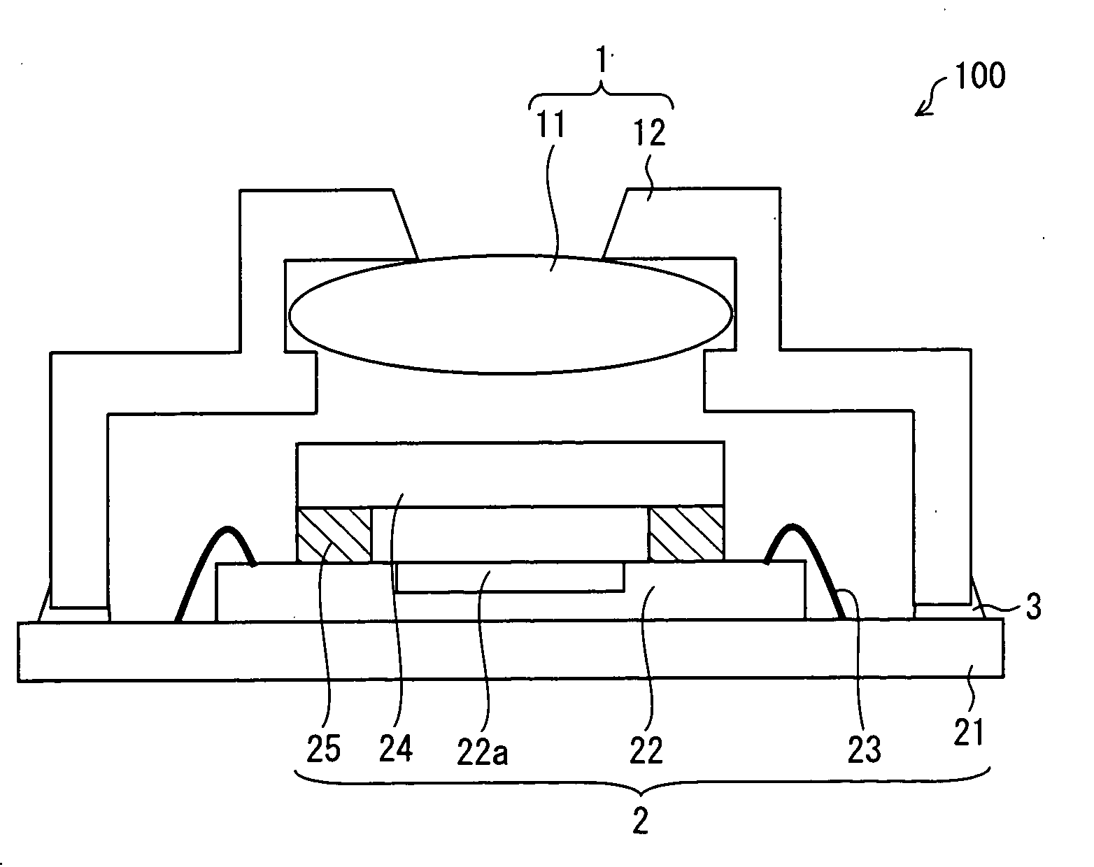
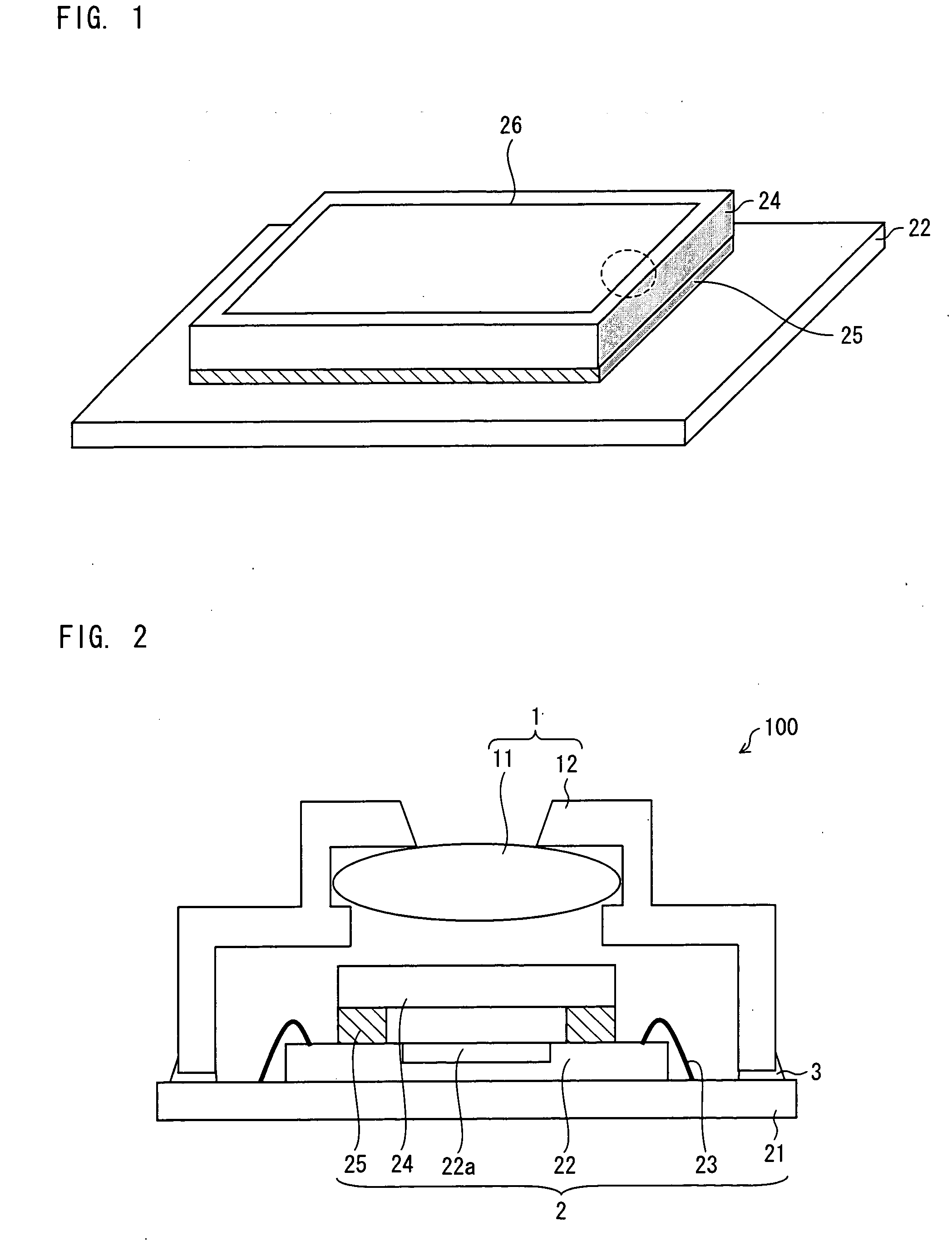
[0049]An embodiment of the present invention is described below with reference to the attached drawings. FIG. 2 is a cross-sectional view illustrating a solid-state image pickup apparatus of the present embodiment.

[0050]A solid-state image pickup apparatus 100 is arranged such that an adhering section 3 adheres a lens section 1 to an image pickup section 2 (see FIG. 2). Note that for simple explanation, the lens section 1 side and the image pickup section 2 side are designated as an upper side and a lower side, respectively.

[0051]The lens section 1 directs external light toward the image pickup section 2. The lens section 1 is arranged such that a hollow lens barrel 12 holds a lens 11 for image pickup inside (see FIG. 2).

[0052]The image pickup section 2 converts a subject image formed by the lens section 1 into an electric signal. Namely, the image pickup section 2 photoelectrically converts light received from the lens section 1. The image pickup section 2 is constituted by a wirin...


PUM


Abstract

A solid-state image pickup apparatus 100 of the present invention includes a transparent cover section 24 which is provided so as to be spaced from a lens section, the transparent cover section 24 being provided (i) so as to face a light-receiving section of a solid-state image sensing device 22 and (ii) so as to have a gap between the solid-state image sensing device 22 and the transparent cover section 24. Furthermore, the transparent cover section 24 is provided with a positioning mark which serves as a reference for positioning the lens section in consideration of the solid-state image sensing device 22. Consequently, it is possible to provide a shock-resistant solid-state image pickup apparatus in which a lens section and an image pickup section are positionally aligned with high accuracy.

Description

[0001]This Nonprovisional application claims priority under 35 U.S.C. §119(a) on Patent Application No. 2008-225081 filed in Japan on Sep. 2, 2008, the entire contents of which are hereby incorporated by reference.TECHNICAL FIELD [0002]The present invention relates to a solid-state image pickup apparatus in which a lens section and an image pickup section are positionally aligned with high accuracy, and to an electronic device including the solid-state image pickup apparatus.BACKGROUND ART [0003]A solid-state image pickup apparatus (camera module) which is applied to a camera of a mobile phone is normally arranged such that a solid-state image sensing device, a digital signal processing device (DSP), a lens, a lens holder, and a camera cone are integrated in a package. Mainly, conventional solid-state image pickup apparatuses are of single-focus type. On the other hand, a solid-state image pickup apparatus has been required, in recent years, to have higher pixel density, higher imag...

Claims


Application Information

Patent Timeline
IPC IPC(8): H04N5/335H04N5/225G02B7/02G03B17/02H04N5/372H04N5/374
CPCG03B17/00H04N5/2257H04N5/2254H04N5/2253H01L2224/48227H04N23/57H04N23/55H04N23/54
Inventor KINOSHITA, KAZUO
Owner SHARP KK
Why Eureka
Try Eureka