Liquid crystal display device

a liquid crystal display and display device technology, applied in non-linear optics, instruments, optics, etc., can solve the problems of increasing the possibility of glass plate breaking, deterioration of visibility in a bright place, and reducing the performance of glass plate, so as to reduce the burden on the environment, reduce waste, and reduce the effect of was

Active Publication Date: 2010-03-04
PANASONIC LIQUID CRYSTAL DISPLAY CO LTD +1
View PDF6 Cites 35 Cited by
  • Summary
  • Abstract
  • Description
  • Claims
  • Application Information

AI Technical Summary

Benefits of technology

[0023]The present invention aims to provide a liquid crystal display device having a structure including a simplified layer structure, which makes good use of a merit obtained by providing a front plate and places little burden on the environment.
[0024]After studying various structures, the present inventor has found that it is possible to reduce a burden to be placed on the environment by attaching a polarizing plate (hereinafter referred to as an image display surface-side polarizing plate), conventionally attached to the liquid crystal panel on the transparent organic medium layer side, to the front plate, instead.
[0030]According to the present invention, one of the polarizing plates (an image display surface-side polarizing plate), which has conventionally been attached to the liquid crystal panel, is attached to the front plate. With the above, a protection film is no longer necessary to be attached to the front plate. This can reduce a waste, a member required, and power consumption, and therefore can advantageously reduce a burden to be placed on the environment.

Problems solved by technology

In the trend of enlarging the size of the screen of a personal computer monitor and a liquid crystal television, there is an increasing possibility of breaking the glass plate even with very small impact as shockproof performance of the glass plate will decrease as the screen size becomes larger while the glass plate thickness remains unchanged.
However, as there is a gap between the front plate and the polarizing plate, significant reflection of ambient scenery on the image display surface is caused due to reflection by three surfaces, namely, the front and back surfaces of the front plate and the surface of the polarizing plate.
This results in deterioration of visibility in a bright place.
The protection film, however, produces a waste of a separate film for protecting the adhesive layer, which resultantly places a burden on the environment.
Moreover, as a transparent organic medium layer, a front plate, and a protection film are provided in addition to a conventional liquid crystal panel, visibility may be deteriorated unless these layers are attached without causing bubbles.
This leads to decrease of yield, and thus increase of the ratio of a liquid crystal panel to be disposed of.
This resultantly places a further burden on the environment.
Moreover, even if the layers can be attached without causing bubbles, an increase of the number of interfaces results in accumulated reflections though reflection on each interface is small, which results in a darker screen image when the same backlight is used.
This leads to increase of power consumption, which again places a further burden on the environment.

Method used


Image

  • Liquid crystal display device
  • Liquid crystal display device
  • Liquid crystal display device

Examples


first embodiment

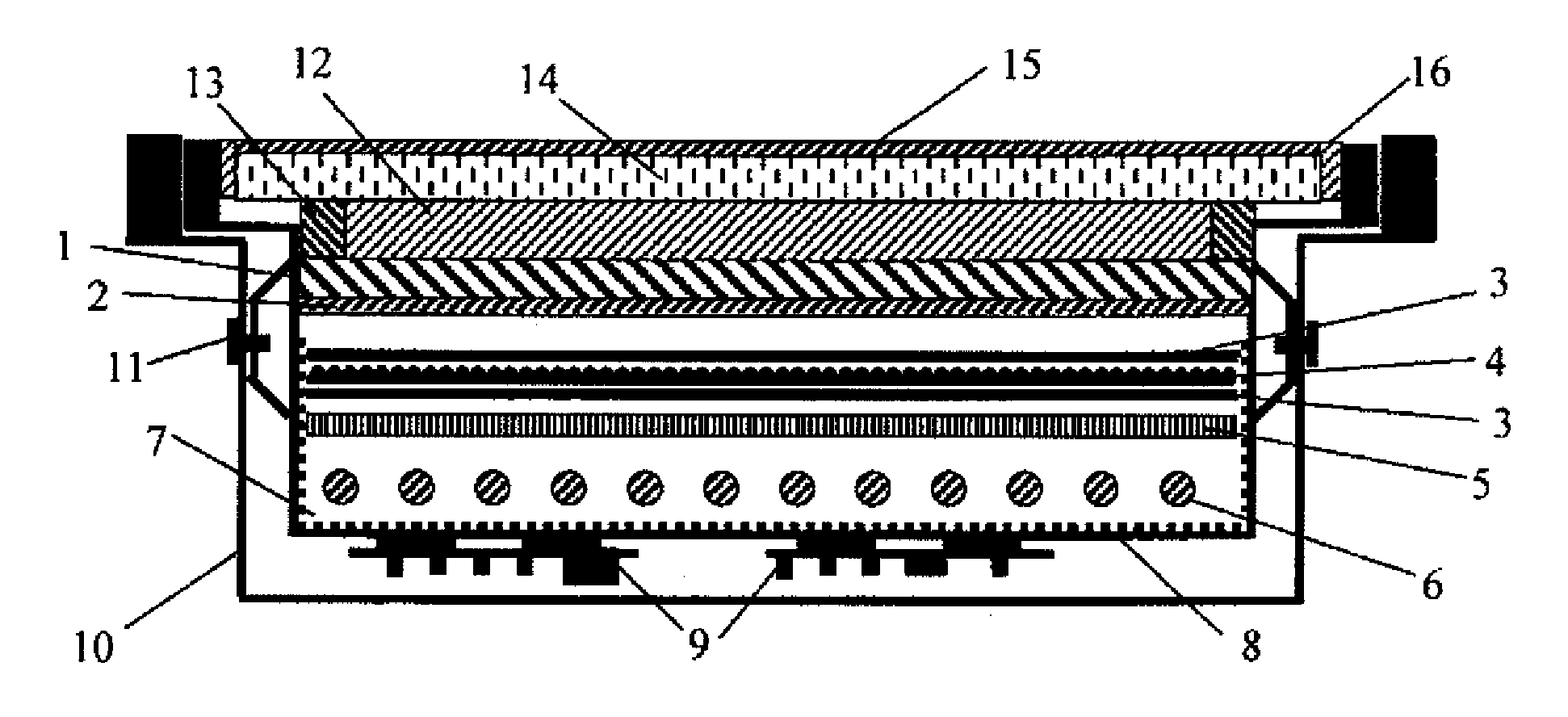
[0076]In the following, a first preferred embodiment for rendering the present invention into practice will be described in detail, referring to FIG. 2.

[0077]In FIG. 2, the polarizing plate 15 incorporates a polyvinyl alcohol layer with iodine doped therein. This component is drawn in one direction through drawing so that the iodine in the polyvinyl alcohol is aligned in one direction.

[0078]The iodine aligned in one direction provides a function for emitting only component in one direction in the incoming light. Also, the forefront surface of the polarizing plate 15 is processed for some extent of waterproof capacity so that the polyvinyl alcohol and iodine in the polarizing plate 15 are prevented from being wet by water when the polarizing plate 15 is wiped with a wet cloth, or the like.

[0079]However, as the polyvinyl alcohol layer having iodine doped therein remains uncovered in the end section of the polarizing plate 15, the end section of the polarizing plate 15 is not waterproo...

second embodiment

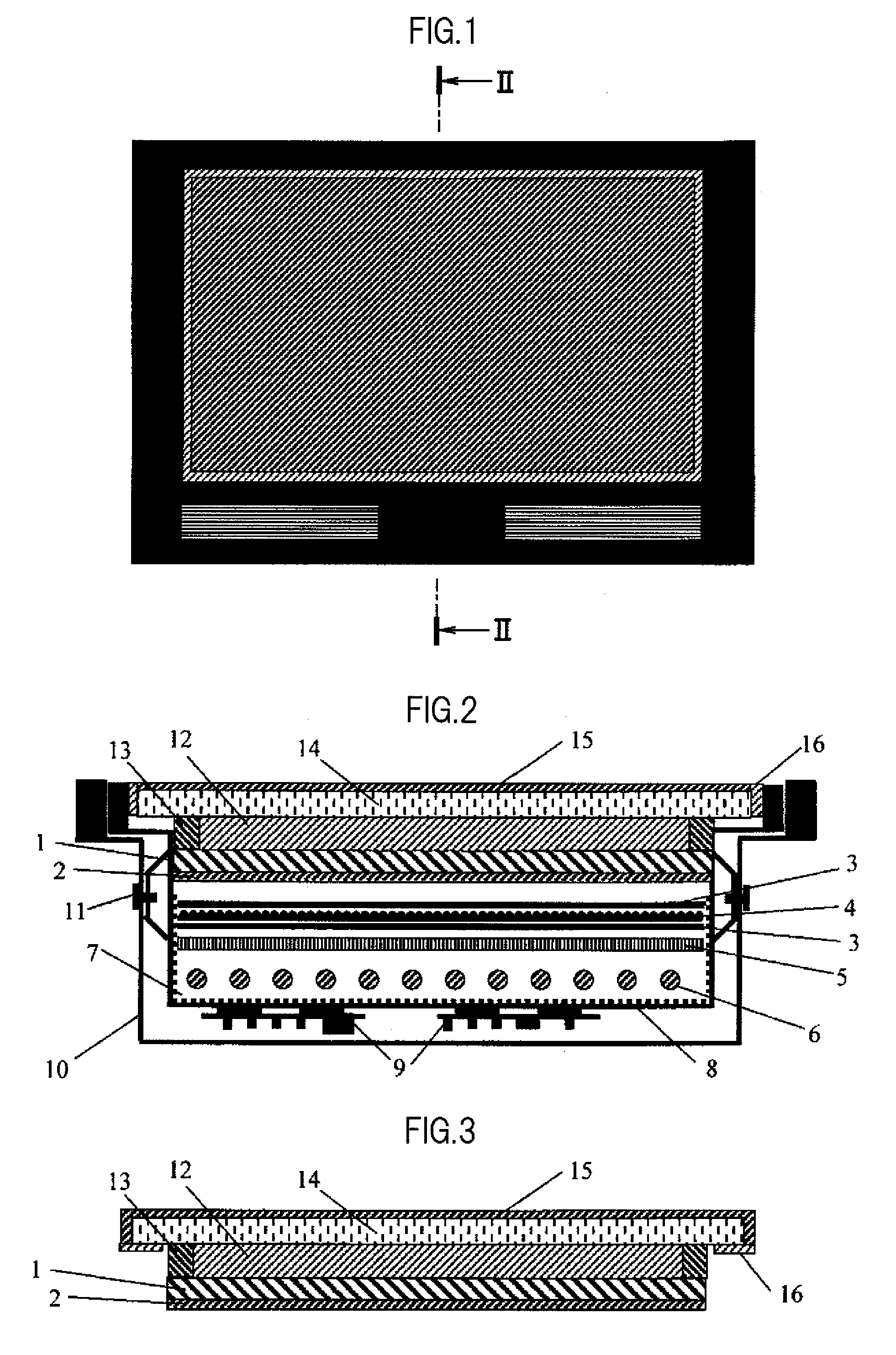
[0086]In the following, a second preferred embodiment for rendering the present invention into practice will be described in detail, referring to FIGS. 3, 4, and 5.

[0087]FIG. 3 is a schematic cross sectional view of the liquid crystal panel 1 for use in a liquid crystal display device according to the second embodiment.

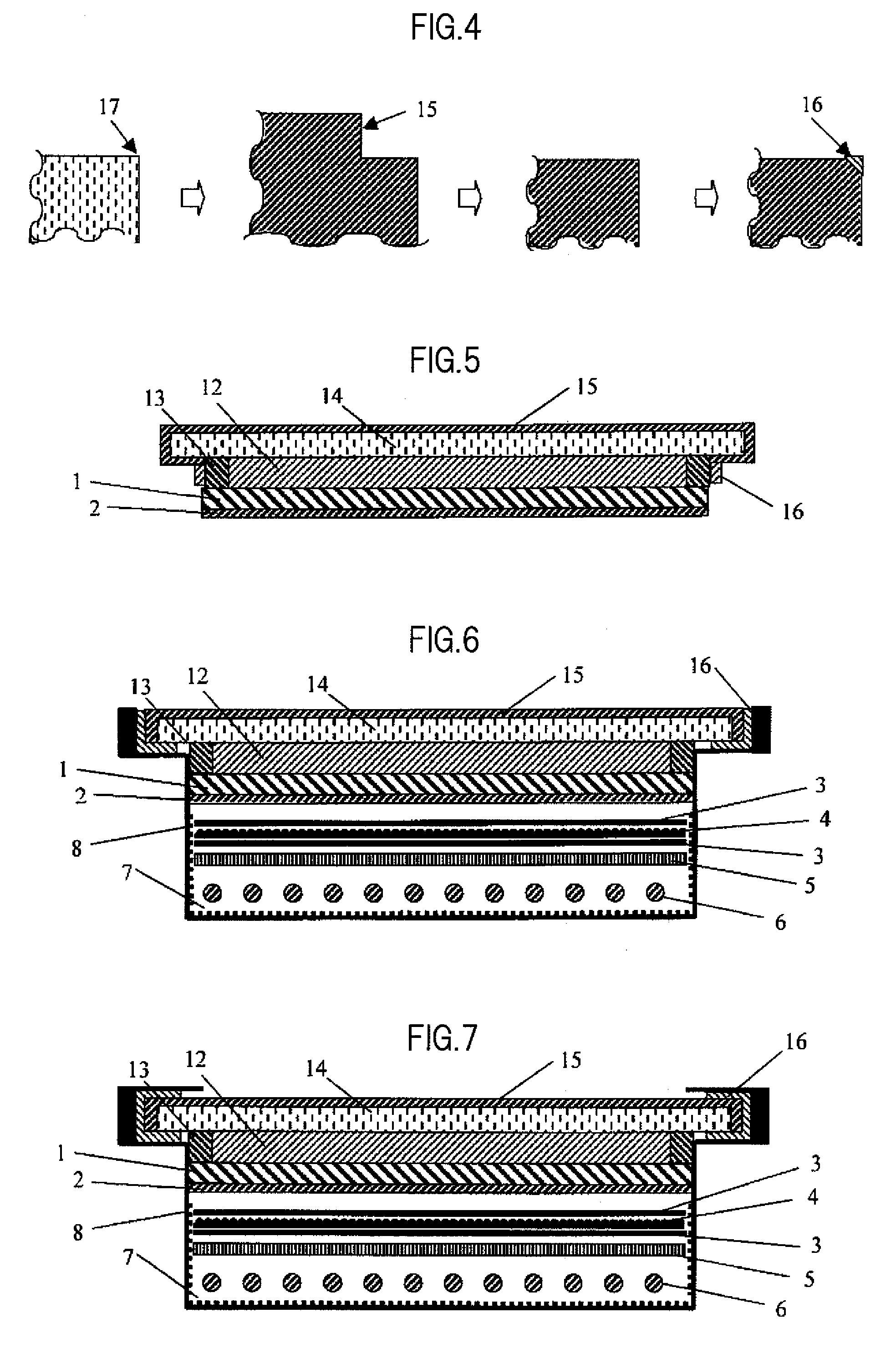
[0088]FIG. 4 is a diagram explaining sealing of an end section of the front plate 14 of the image display surface-side polarizing plate 15.

[0089]FIG. 5 is a schematic cross sectional view of the liquid crystal panel 1 for use in a liquid crystal display device according to the second embodiment.

[0090]When an image display surface-side polarizing plate 15 is attached to the front plate 14, the polarizing plate 15 is sealed on the lateral surface of the front plate 14 in FIG. 2. In this case, if the sealing resin is resulted flat along the surface of the front plate 14, the polarizing plate 15 can be wiped with a wet cloth, or the like, without catching the cloth, and d...

third embodiment

[0097]In the following, a third preferable embodiment for rendering the present invention into practice will be described in detail, referring to FIG. 6.

[0098]FIG. 6 is a schematic cross sectional view of a liquid crystal panel 1 for use in a liquid crystal display device according to the third embodiment.

[0099]As shown in FIG. 6, the end section of the image display surface-side polarizing plate 15 is folded into between the lateral surface of the front plate 14 and the liquid crystal module, and the polarizing plate 15, the front plate 14, and the liquid crystal module are bound together, using sealing resin, when sealing. With the above, not only sealing of the end section of the polarizing plate 15, but also binding between the liquid crystal panel 1 having the front plate 14 attached thereon and the liquid crystal module can be achieved at the same time. This can enhance productivity.


PUM

PropertyMeasurementUnit
thicknessaaaaaaaaaa
transparentaaaaaaaaaa
reflectionaaaaaaaaaa

Abstract

A liquid crystal display device has a liquid crystal display module including a backlight unit and a liquid crystal panel; a first polarizing plate attached to a side of the liquid crystal panel, the side facing the backlight unit; a transparent front plate mounted on a side of the liquid crystal panel, the side not facing the backlight unit; a transparent organic medium layer placed between the front plate and the liquid crystal panel; and a second polarizing plate attached to a surface of the front plate, the surface opposite from a surface thereof closer to the transparent organic medium layer. An end section of the second polarizing plate is sealed using resin so as not to be directly exposed to air.

Description

CROSS-REFERENCE TO RELATED APPLICATION[0001]The present application claims priority from Japanese application JP2008-226656 filed on Sep. 4, 2008, the content of which is hereby incorporated by reference into this application.BACKGROUND OF THE INVENTION[0002]1. Field of the Invention[0003]The present invention relates to a liquid crystal display device, and specifically to a liquid crystal display device having a transparent front plate attached to an image display surface.[0004]2. Description of the Related Art[0005]In a liquid crystal display device using liquid crystal, light from a light source is recognized as an image after having passed through a liquid crystal layer, a color filter, a polarizing plate, and so forth.[0006]In the above, a polarizing plate is used for the forefront surface of a liquid crystal display device used for a monitor of a personal computer or a liquid crystal television, and an anti-glare (AG) film having fine concaves and convexes formed thereon or a ...

Claims


Application Information

Patent Timeline
Patent Type & Authority Applications(United States)
IPC IPC(8): G02F1/1335
CPCG02F2201/503G02F1/133308
Inventor SASAKI, HIROSHI
Owner PANASONIC LIQUID CRYSTAL DISPLAY CO LTD
Why Eureka
Try Eureka