

Adhesive composition for optical filter, optical filter and display device
a technology of adhesive composition and optical filter, applied in the direction of adhesive types, optical elements, instruments, etc., can solve the problems of easy deterioration of ultraviolet light, inability to obtain vivid red color, and malfunction of peripheral devices, so as to reduce the cost of production process, prevent discoloration of electroconductive mesh surface, and simplify production process
- Summary
- Abstract
- Description
- Claims
- Application Information
AI Technical Summary
Benefits of technology
Problems solved by technology
Method used
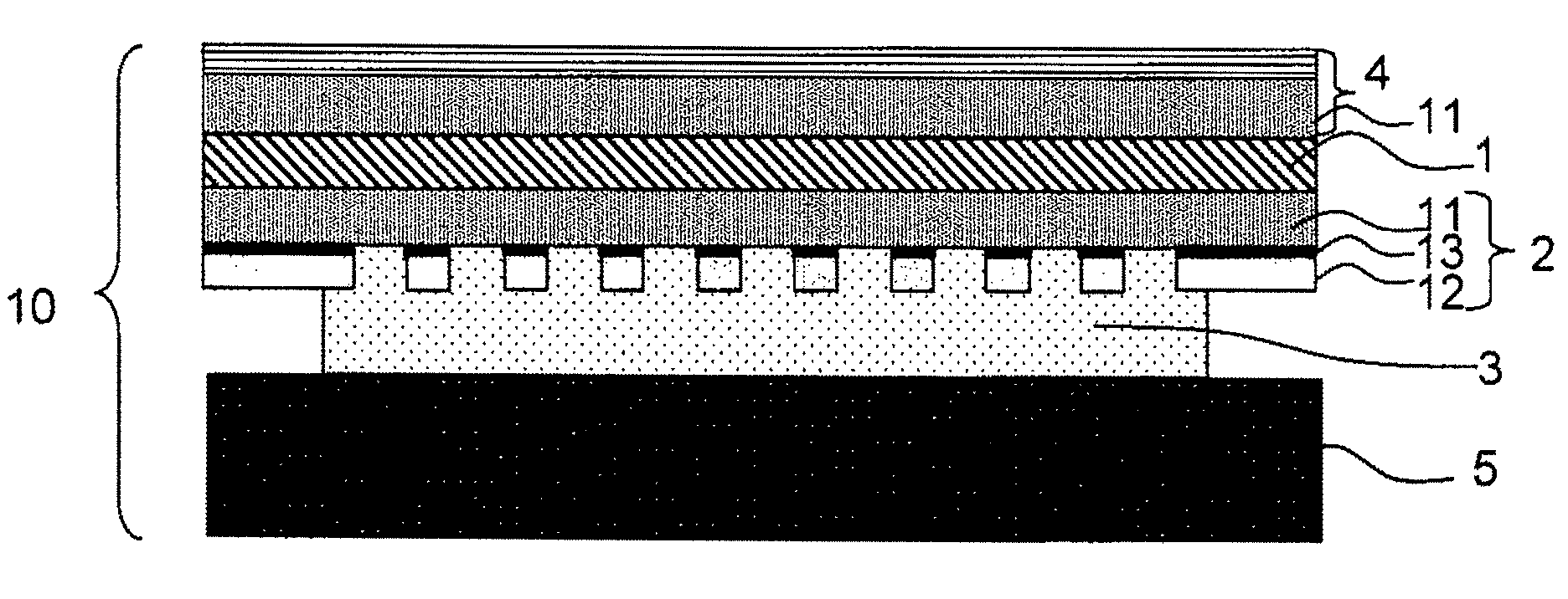
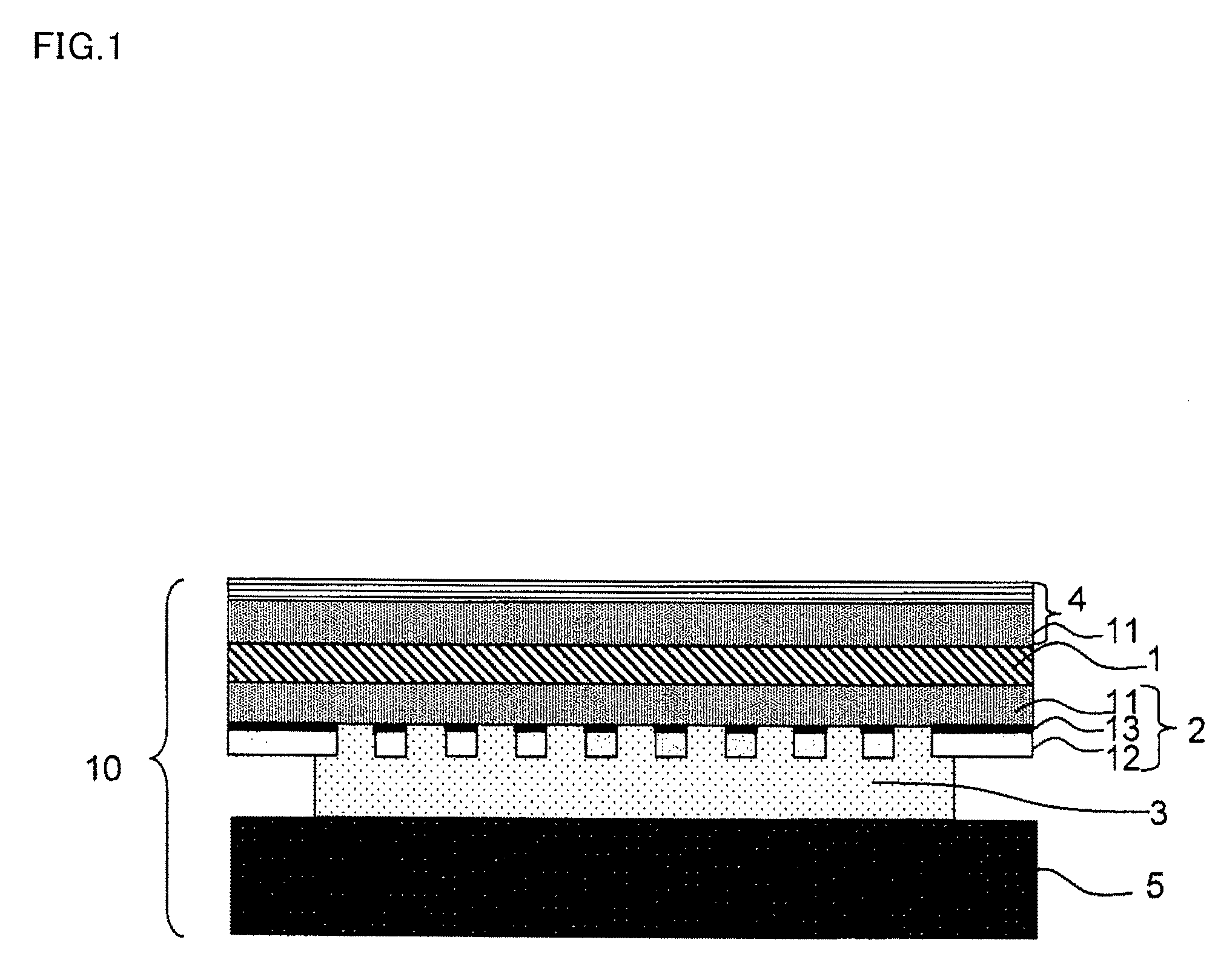
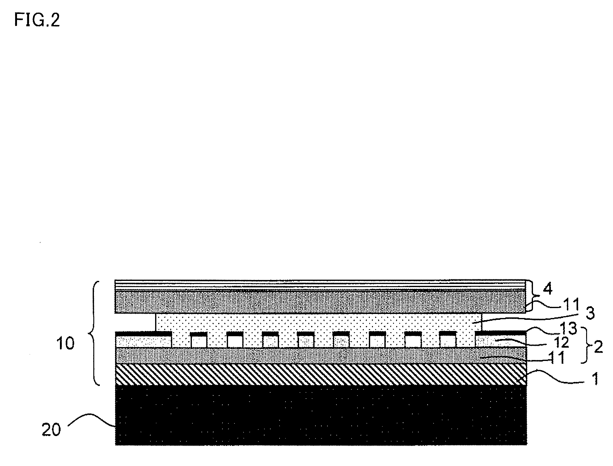
Image

Examples
example 1
[0265]A purified material having purity of 98% or more was used for each monomer used for the polymerization described below.
[0266]Monomers including ethyl acrylate, methyl acrylate, butyl acrylate, isobutyl acrylate and 2-hydroxylethyl methacrylate were copolymerized using ethyl acetate as a solvent and PERBUTYL O (product name, manufactured by NOF Corporation) as a polymerization initiator. Acid number of carboxyl group residue was measured and evaluated in accordance with JIS K2501. The acid number was 0. Thus, an acrylic copolymer (A) substantially not containing a carboxyl group residue was obtained. With respect to 100 parts by mass of the acrylic copolymer (A), 0.2 parts by mass of near-infrared light absorbing agent EXCOLOR IR-10A (product name, manufactured by Nippon Shokubai Co., Ltd.; a phthalocyanine-based compound), 0.02 parts by mass of EXCOLOR 906B (product name, manufactured by Nippon Shokubai Co., Ltd.; a phthalocyanine-based compound), 0.08 parts by mass of EXCOLOR...
example 2
[0278]Except that 0.2 parts by mass of near-infrared light absorbing agent EXCOLOR IR12 (product name, manufactured by Nippon Shokubai Co., Ltd.; a phthalocyanine-based compound), 0.1 part by mass of near-infrared light absorbing agent IR14 (product name, manufactured by Nippon Shokubai Co., Ltd.; a phthalocyanine-based compound), and 0.4 parts by mass of KayasorbIRG-068 (product name, manufactured by NIPPON KAYAKU CO., Ltd.; a diimmonium-based compound) with respect to 100 parts by mass of the acrylic copolymer (A) were used as the light absorbing agents, an adhesive composition for an optical filter was prepared similarly as in Example 1.
[0279]The adhesive composition was coated on a release-treated PET (product name: E7002, manufactured by Toyobo Co., Ltd.) having a thickness of 100 μm to have a film thickness of 25 μm when dried with the use of an applicator. After drying at 100° C. for 2 minutes, a release-treated PET film of 100 μm was laminated from the top and an optical fil...
example 3
[0281]Except that 0.2 parts by mass of near-infrared light absorbing agent EXCOLOR IR-10A (product name, manufactured by Nippon Shokubai Co., Ltd.; a phthalocyanine-based compound), 0.02 parts by mass of near-infrared light absorbing agent EXCOLOR 906B (product name, manufactured by Nippon Shokubai Co., Ltd.; a phthalocyanine-based compound), 0.08 parts by mass of near-infrared light absorbing agent EXCOLOR 910B (product name, manufactured by Nippon Shokubai Co., Ltd.; a phthalocyanine-based compound), 0.045 parts by mass of neon light absorbing agent (product name: TAP-2, manufactured by YAMADA KAGAKU Co., Ltd.; a tetraazaporphyrin base dye), and 0.3 parts by mass of color correction dye (product name: KAYASET RED A2G, manufactured by NIPPON KAYAKU CO., Ltd.) with respect to 100 parts by mass of the acrylic copolymer (A) were used as the light absorbing agents, an adhesive composition for an optical filter was prepared similarly as in Example 1.
[0282]The adhesive composition was co...
PUM
| Property | Measurement | Unit |
|---|---|---|
| wavelength | aaaaa | aaaaa |
| wavelength | aaaaa | aaaaa |
| wavelength | aaaaa | aaaaa |
Abstract
Description
Claims
Application Information