Laser illuminating device and image display device

a technology of laser illumination and image display, which is applied in the direction of lenses, instruments, optical elements, etc., can solve the problems of limited reproducing area, low light use efficiency, and short life of lasers

Inactive Publication Date: 2010-03-04
PANASONIC CORP
View PDF19 Cites 150 Cited by
  • Summary
  • Abstract
  • Description
  • Claims
  • Application Information

AI Technical Summary

Benefits of technology

[0016]According to the invention, since each of the plurality of the microlenses is operable to expand the laser light emitted from the laser light source for superimposition, speckle noises in a diffraction field and an image field can be removed. Further, each of the plurality of the microlenses having the predetermined numerical aperture in the in-plane direction is operable to uniformly illuminate an illumination plane. Furthermore, since the plurality of the microlenses of the first lens are operable to expand the laser light emitted from the laser light source and superimpose the expanded laser light, there is no need of providing plural optical systems such as an optical system for expanding laser light and a relay optical system for superimposing laser light. This enables to realize miniaturization.

Problems solved by technology

The lamp light source, however, has drawbacks that the life is short, the color reproducing area is limited, the light source area is large, and the light use efficiency is low.
However, in a projection display incorporated with a laser light source, speckle noise may be generated resulting from high interference of laser light.
The former speckle noise in a diffraction field causes a problem in an exposing machine and an illuminating optical system, and both of the speckle noise in a diffraction field and the speckle noise in an image field cause a problem in a projection display incorporated with a laser light source.
However, the optical system proposed in patent literature 1 has a size as large as the size of an optical system required in a lamp light source, and accordingly, miniaturization of the optical system is difficult.
However, in patent literature 2, sufficient miniaturization of an optical system has not been achieved, and the number of parts is increased.
However, the aforementioned elements have a restriction on the use wavelength and the incident angle, and it is difficult to make the light intensity uniform or perform accurate beam shaping with respect to a multi-wavelength light source or plural light sources.
Thus, there is a serious problem to overcome in fabricating a portable projector utilizing a characteristic of a laser light source.

Method used


Image

  • Laser illuminating device and image display device
  • Laser illuminating device and image display device
  • Laser illuminating device and image display device

Examples


first embodiment

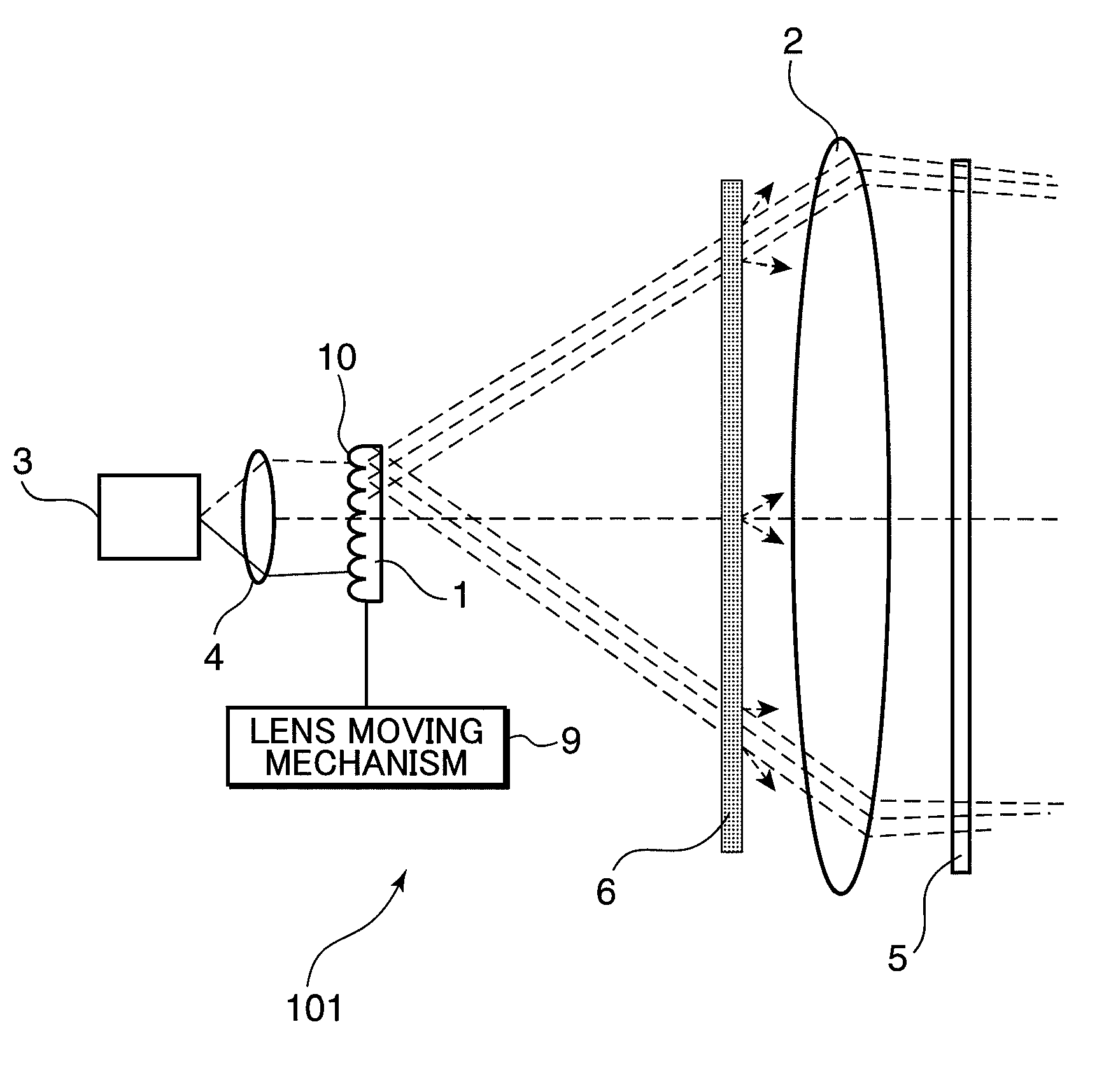
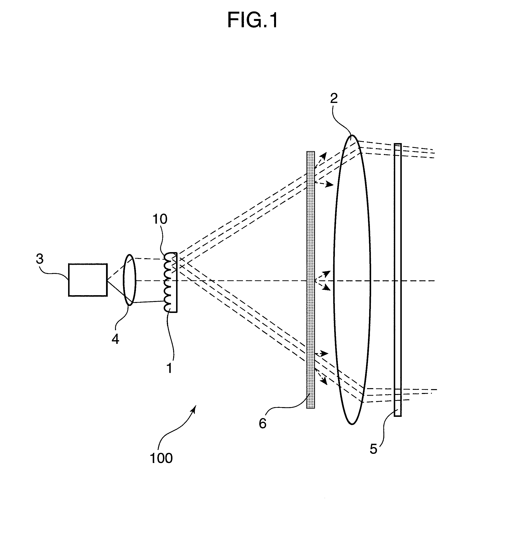
[0034]FIG. 1 is a schematic diagram showing an arrangement of a laser illuminating device 100 in the first embodiment of the invention. The laser illuminating device 100 shown in FIG. 1 is an illuminating device incorporated with a laser light source.

[0035]The laser illuminating device 100 includes a first lens 1, a second lens 2, a laser light source 3, a collimator lens 4, and a light diffuser 6.

[0036]The laser light source 3 emits laser light. In the first lens 1, a plurality of microlenses 10 each having a predetermined numerical aperture (NA) in the in-plane direction are arranged in such a manner as to expand the laser light emitted from the laser light source 3 to thereby superimpose the laser light transmitted through each of the microlenses 10.

[0037]Laser light emitted from the laser light source 3 is collimated by the collimator lens 4, and then incident into the first lens 1 constituted of plural lens arrays each formed of a predetermined number of microlenses 10. The las...

second embodiment

[0081]FIG. 7 is a schematic diagram showing an arrangement of a color image display device 210 in the second embodiment of the invention. The color image display device 210 in the second embodiment includes a color laser illuminating device 200 incorporated with a 3-wavelength laser light source. Elements having the same arrangement as the corresponding elements in the first embodiment are indicated with the same reference numerals as the corresponding elements, and description thereof is omitted herein.

[0082]The color image display device 210 includes the color laser illuminating device 200, a two-dimensional light modulator 5a, a projection lens 7, and a screen 8. The color laser illuminating device 200 includes a first lens 1, a second lens 2, laser light sources 3R, 3G, and 3B, a collimator lens 4, a light diffuser 6, a cross prism 12, and a dichroic mirror 13.

[0083]The laser light source 3R is a red semiconductor laser for emitting red laser light. The laser light source 3G is ...

third embodiment

[0093]In this section, a laser illuminating device in the third embodiment is described. The laser illuminating device in the third embodiment is different from the laser illuminating device in the first embodiment solely in the arrangement of the first lens. Accordingly, in the following, solely the first lens 1 is described. FIG. 8A is an enlarged view showing a first lens in the third embodiment of the invention, and FIG. 8B is an enlarged view showing one of microlenses shown in FIG. 8A.

[0094]A first lens 1a in the third embodiment is constituted of microlenses 10a having different pitches. The respective microlenses 10a have a predetermined identical NA in the in-plane direction. Each of the microlenses 10a in the third embodiment includes a first cylindrical lens portion 12a which is formed in a horizontal direction on the laser light incident side of the microlens 10a, with a first NA; and a second cylindrical lens portion 12b which is formed in a vertical direction on the la...


PUM


Abstract

An object of the invention is to provide a laser illuminating device and an image display device that enable to remove speckle noises in a diffraction field and an image field, uniformly illuminate an illumination plane, and realize miniaturization. A laser illuminating device 100 includes a laser light source 3, a first lens 1 including a plurality of microlenses 10 each having a predetermined numerical aperture in an in-plane direction, each of the microlenses 10 being adapted to expand laser light emitted from the laser light source 3 to thereby superimpose the laser light transmitted through each of the microlenses 10; and a second lens 2 having an effective diameter larger than an effective diameter of the first lens 1, and for compensating for a divergence angle of the laser light expanded by each of the plurality of the microlenses 10.

Description

TECHNICAL FIELD[0001]The present invention relates to a laser illuminating device incorporated with a laser as a light source, and an image display device such as a projection display incorporated with the laser illuminating device.BACKGROUND ART[0002]In recent years, there has been widely used an image display device such as a projection display for displaying an image on a screen. Generally, a lamp light source is used in the projection display. The lamp light source, however, has drawbacks that the life is short, the color reproducing area is limited, the light source area is large, and the light use efficiency is low.[0003]In order to solve the above drawbacks, there is proposed an idea of using a laser light source as a light source in an image display device. Since the laser light source has a long life and a strong light directivity, as compared with a lamp light source, the light use efficiency can be easily increased. Since the laser light source emits monochromatic light, ...

Claims


Application Information

Patent Timeline
Patent Type & Authority Applications(United States)
IPC IPC(8): G02B27/48G02B27/12G02B5/02
CPCG02B3/0006G02B27/48G03B21/14H04N9/3197H04N9/3152H04N9/3161H04N9/3102G03B21/2033G03B21/208
Inventor MIZUSHIMA, TETSUROKASAZUMI, KENICHIITOH, TATSUOSHIKII, SHINICHI
Owner PANASONIC CORP
Why Eureka
Try Eureka