Three-dimensional display apparatus

a display device and three-dimensional technology, applied in the field of three-dimensional (“ 3d”) image display devices, can solve the problems of stereoscopic image use in movie theaters, and the general limitation of stereoscopic schemes, and achieve the effects of reducing the number of air layers, reducing the reflection of surrounding light, and improving transmittan

Inactive Publication Date: 2010-03-04
SAMSUNG DISPLAY CO LTD
View PDF8 Cites 8 Cited by
  • Summary
  • Abstract
  • Description
  • Claims
  • Application Information

AI Technical Summary

Benefits of technology

[0028]According to the present invention, resolution of the same degree as the front direction is maintained when increasing the viewing angle such that the 3D wide viewing angle may be realized, and the number of air layers between the panel and the module outermost surface is reduced such that transmittance may be improved. Also, the number of air layers is reduced such that the reflection of surrounding light is reduced and visibility is improved, and the number of component elements is reduced to thereby realize a reduction of weight and thickness of the 3D module.

Problems solved by technology

However, due to a drawback that the polarization spectacles or liquid crystal shutter spectacles must be worn, the stereoscopic schemes are not commonly used, and the stereoscopic schemes are typically limited to use in movie theatres.
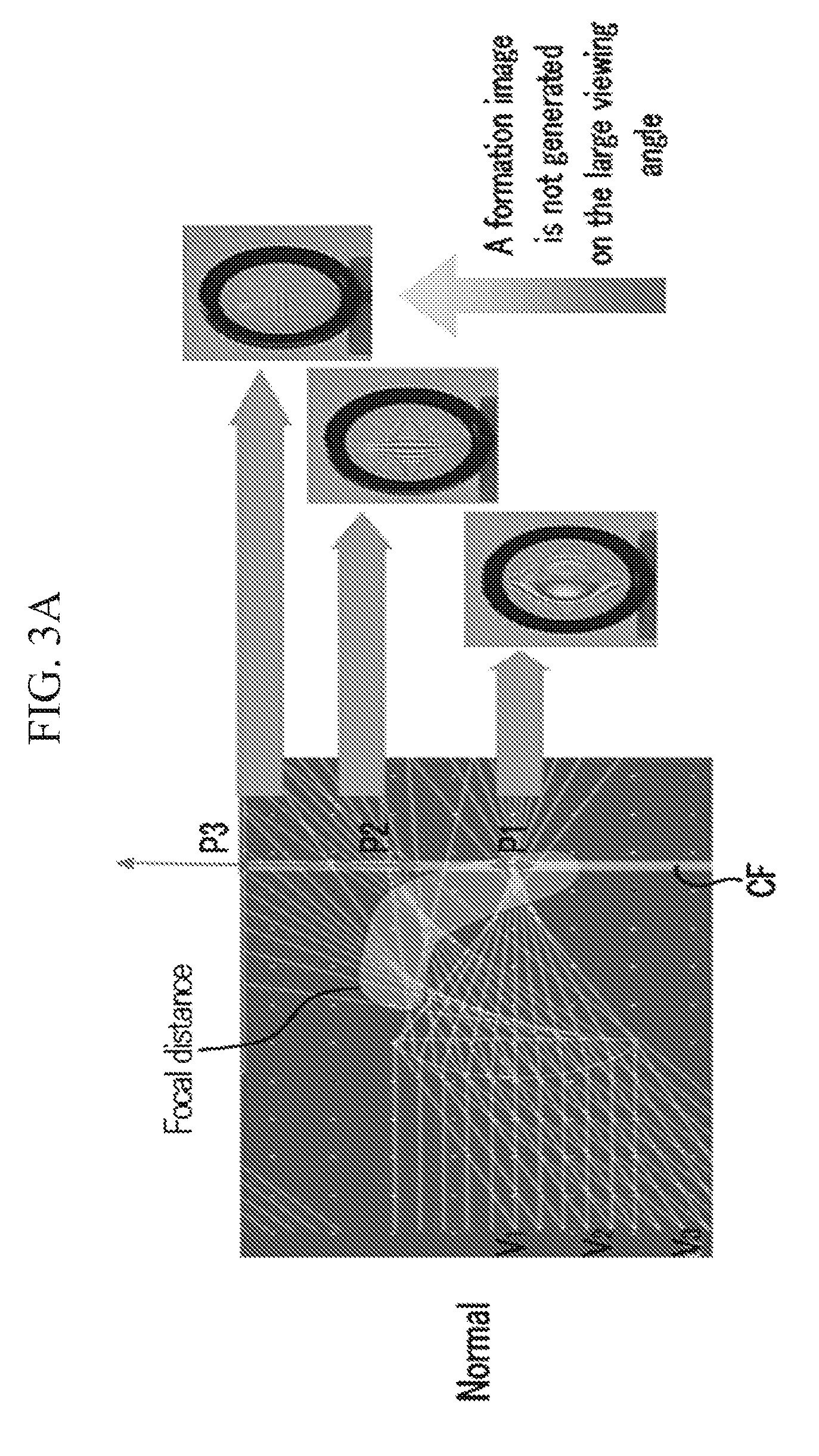
Also, if the viewing angle is increased, the 3D visible region where the stereoscopic image can be shown is limited by increasing confusion between images viewed at each position within the viewing angle such that it is necessary to expand the 3D visible region through the wide viewing angle.

Method used


Image

  • Three-dimensional display apparatus
  • Three-dimensional display apparatus
  • Three-dimensional display apparatus

Examples


Embodiment Construction

[0035]The invention now will be described more fully hereinafter with reference to the accompanying drawings, in which exemplary embodiments of the invention are shown. This invention may, however, be embodied in many different forms and should not be construed as limited to the embodiments set forth herein. Rather, these embodiments are provided so that this disclosure will be thorough and complete, and will fully convey the scope of the invention to those skilled in the art. Like reference numerals refer to like elements throughout.

[0036]It will be understood that when an element is referred to as being “on” another element, it can be directly on the other element or intervening elements may be present therebetween. In contrast, when an element is referred to as being “directly on” another element, there are no intervening elements present. As used herein, the term “and / or” includes any and all combinations of one or more of the associated listed items.

[0037]It will be understood ...


PUM


Abstract

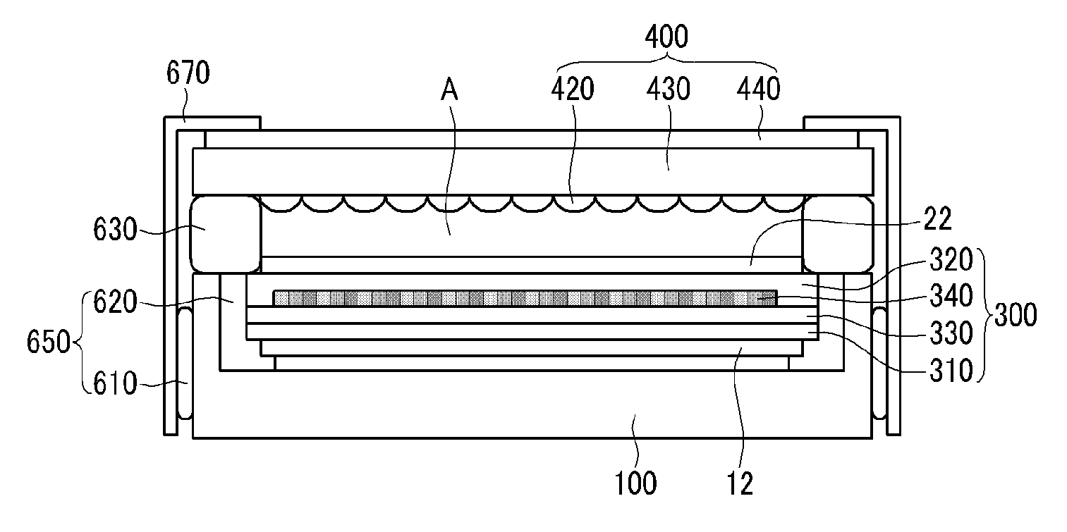
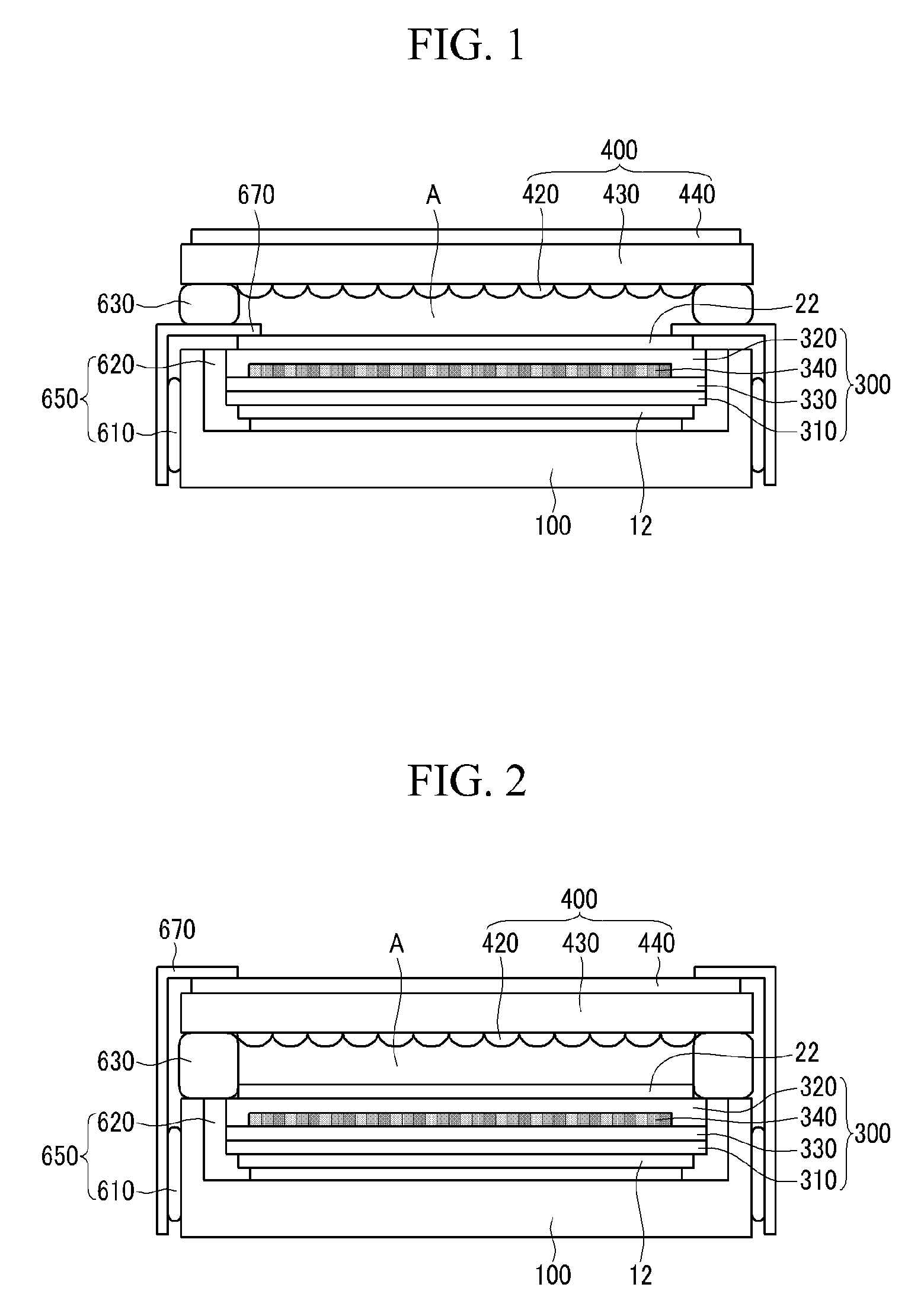
A display device includes; a display panel, a lens substrate facing the display panel, an air layer disposed between the display panel and the lens substrate, and a light refraction portion disposed on a surface of the lens substrate facing the display panel, wherein an average refractive index of the light refraction portion taken along a plane substantially parallel to the display panel increases in a direction substantially parallel to a path of light from the display panel to the lens substrate.

Description

[0001]This application claims priority to Korean Patent Application No. 10-2008-0084441, filed on Aug. 28, 2008, and all the benefits accruing therefrom under 35 U.S.C. §119, the contents of which in its entirety are herein incorporated by reference.BACKGROUND OF THE INVENTION[0002](a) Field of the Invention[0003]The present invention relates to a three-dimensional (“3D”) image display device having a reverse phase lens structure.[0004](b) Description of the Related Art[0005]Fast communication services based on the information superhighway are expected to evolve from simpler audio-based services, such as a current telephone service, to audible and visual multimedia services utilizing digital terminals processing characters, voices, and images quickly. Such services are eventually expected to be applied to 3D communication services that enable realistic and stereoscopic viewing and hearing, overcoming temporal and spatial limitations.[0006]Typically, a 3D image is expressed by a prin...

Claims


Application Information

Patent Timeline
Patent Type & Authority Applications(United States)
IPC IPC(8): G02B27/22G02B30/27
CPCG02F1/133502G02B27/2214G02B30/27G02B3/00G02F1/1335G02F1/133562G02F1/133567G02F1/133526G02F1/133528
Inventor YUN, HAE-YOUNGJUNG, KYUNG-HOLEE, SEUNG-HOONKIM, SUNG-WOONLU, JIANGANGKIM, HEE-SEOP
Owner SAMSUNG DISPLAY CO LTD
Why Eureka
Try Eureka