Stacked multilayer capacitor

a multi-layer capacitor and ceramic technology, applied in the field of stacked ceramic capacitors, can solve the problems of high heat transfer coefficient, high heat conduction coefficient, and high power transfer of stacked capacitors, so as to improve heat transfer, improve heat transfer efficiency, and reduce heat loss

Active Publication Date: 2010-03-04
DEVOE DANIEL +2
View PDF20 Cites 17 Cited by
  • Summary
  • Abstract
  • Description
  • Claims
  • Application Information

AI Technical Summary

Benefits of technology

[0011]The present invention provides a stacked multilayer capacitor that substantially improves heat transfer from the capacitor, is tolerant of thermal stresses caused by expansion and contraction, is resistant to vibration and mechanical shock conditions and has a low inductance. The stacked multilayer capacitor has a split lead frame that provides larger areas in electrical contact with the capacitor and a substrate to substantially improve heat transfer from the capacitor and provide an improved tolerance to thermal stresses resulting from expansion and contraction. Further, the split lead frame may optionally be used to attach the stacked multilayer capacitor to the substrate with fasteners, thereby making it more tolerant to vibration and mechanical shock. In addition, the split lead frame facilitates mounting the stacked multilayer capacitor on the substrate in an orientation that reduces inductance.

Problems solved by technology

The stacked capacitors may carry high power due to high ripple current from switching transistors.
Heat conduction from the top of the stack down to the circuit board 30 may be very inefficient.
However, since the temperature in the vicinity of the source changes greatly when the source is turned on and off, a significant amount of thermal stress occurs at a ceramic capacitor mounted on the aluminum substrate, which has a high coefficient of thermal expansion.
This thermal stress may cause cracking to occur at the ceramic capacitor, which, in turn, may induce problems such as shorting defects and arcing.
Further concerns about the performance of stacked capacitors arise under vibration and mechanical shock conditions.
The stacks may be tall and heavy.
When used in a satellite or rocket, there is a legitimate concern of the part falling off of the circuit board, or at least of the solder joints cracking or breaking loose resulting from excessive vibrations and extreme environmental conditions.
Many designers resort to using an epoxy to help adhere the capacitor to the board, but this is not optimal because the epoxy itself might cause problems, such as thermal stresses, under certain temperature conditions due to the expansion or contraction of the epoxy.
Because the beam lead arrangement does not contain interior plates, it does not benefit from the advantages of multilayer capacitors.

Method used


Image

  • Stacked multilayer capacitor
  • Stacked multilayer capacitor
  • Stacked multilayer capacitor

Examples


Embodiment Construction

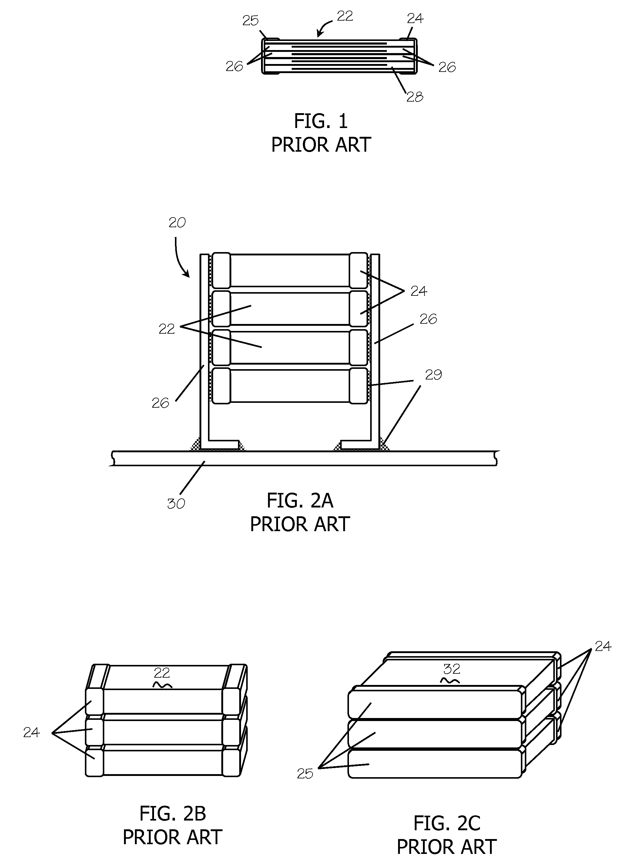
[0053]Embodiments of the present invention address the problems in the prior art by providing stacked multilayer capacitors with improved vibration, inductance and thermal characteristics as well as improved single multilayer capacitors. The multilayer capacitors may be of the type illustrated in FIG. 1.

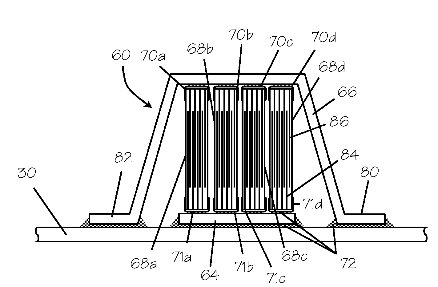
[0054]Turning now to the remaining drawings, wherein like numbers denote like parts throughout the several views, FIGS. 4 and 5 illustrate an exemplary embodiment of the stacked multilayer capacitor. The stacked multilayer capacitor 60 is composed of a split lead frame 62 having a bottom lead frame 64 containing a bottom plate and a top lead frame 66. The lead frame 62 electrically connects one or more multilayer capacitors 68a-68d having respective conductive end terminations 70a-70d, 71a-71d. The multilayer capacitors 68a-68d may be capacitors similar to capacitor 22 or 32 known in the art and discussed above (FIGS. 1, 2B, and 2C). As discussed above, the aspect ratios of the multi...


PUM


Abstract

A capacitor device mountable on a plane of a substrate includes an electrically conductive bottom plate adapted to be mounted substantially parallel to, and in electrical contact at the plane of the substrate and a first multilayer capacitor having substantially parallel first and second electrode plates oriented substantially perpendicular to the bottom plate with the first electrode plates being electrically connected to the bottom plate. An electrically conductive top lead frame overlaps with, and is electrically isolated from, the bottom plate. The top lead frame electrically connected to the second electrode plates and adapted to be electrically connected at the plane of the substrate. The bottom lead frame may have a corrugated shape, where the corrugated shape provides compliance between the first multilayer capacitor and the substrate. A portion of the top lead frame may contact at least a portion of a side of the first multilayer capacitor.

Description

CROSS-REFERENCE TO RELATED APPLICATIONS[0001]This application is a continuation-in-part of U.S. application Ser. No. 12 / 245,926, entitled “STACKED MULTILAYER CAPACITOR,” filed Oct. 6, 2008, which is a continuation in part of U.S. application Ser. No. 11 / 753,090, entitled “STACKED MULTILAYER CAPACITOR,” filed May 24, 2007, the entireties of which are incorporated by reference herein.FIELD OF THE INVENTION[0002]The present invention relates generally to stacked ceramic capacitors and more specifically, to mounting a stacked ceramic capacitor to a substrate.BACKGROUND OF THE INVENTION[0003]Multilayer ceramic chips 22 (FIG. 1) are common capacitors used for bypass, coupling, or energy storage applications in electronic circuits. The chips 22 include internal parallel plates 26 in dielectric body 28 such as a ceramic. The parallel plates are connected by terminations 24, 25 on the outer edges of the chip 22. End terminations 24, 25 electrically connect each of the respective internal ele...

Claims


Application Information

Patent Timeline
Patent Type & Authority Applications(United States)
IPC IPC(8): H01G4/228
CPCH01G4/232H01G4/30H01G4/38H05K1/0231H05K2201/10946H05K3/3421H05K2201/10515H05K2201/10537H05K2201/10636H05K1/181Y02P70/50
Inventor DEVOE, DANIELDEVOE, ALANDEVOE, LAMBERT
Owner DEVOE DANIEL
Why Eureka
Try Eureka