Lighting device for vehicle

a technology for lighting devices and vehicles, applied in the direction of lighting support devices, fixed installations, lighting and heating apparatus, etc., can solve the problems of difficult to use such a related art lighting device in a vehicle, subunits and second subunits having separate structures in the transverse direction of projection lenses, etc., to achieve excellent condition and reduce size

Inactive Publication Date: 2010-03-04
KOITO MFG CO LTD
View PDF6 Cites 30 Cited by
  • Summary
  • Abstract
  • Description
  • Claims
  • Application Information

AI Technical Summary

Benefits of technology

[0005]Exemplary embodiments of the present invention provide a lighting device for a vehicle which ca...

Problems solved by technology

In the related art lighting device described in the JP-A-2007-213879 Publication, however, there is a disadvantage in that the first subunit and the second subunit have separate structures in a ...

Method used


Image

  • Lighting device for vehicle
  • Lighting device for vehicle
  • Lighting device for vehicle

Examples


first exemplary embodiment

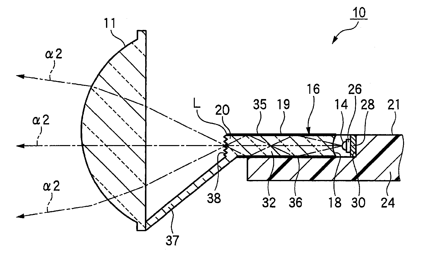
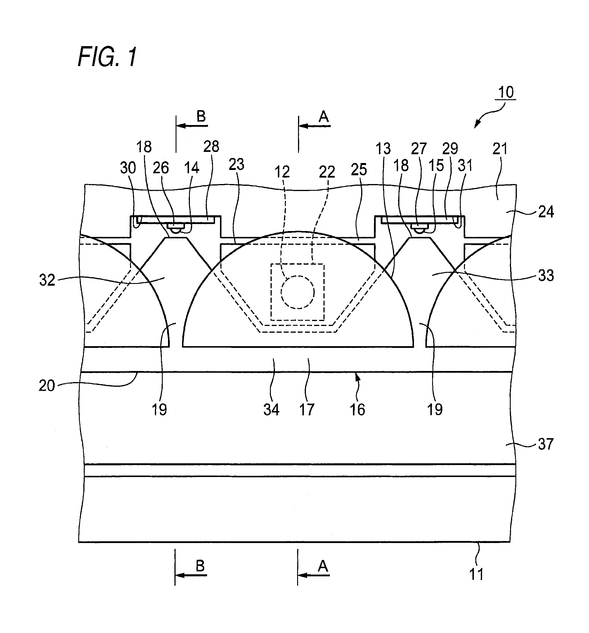
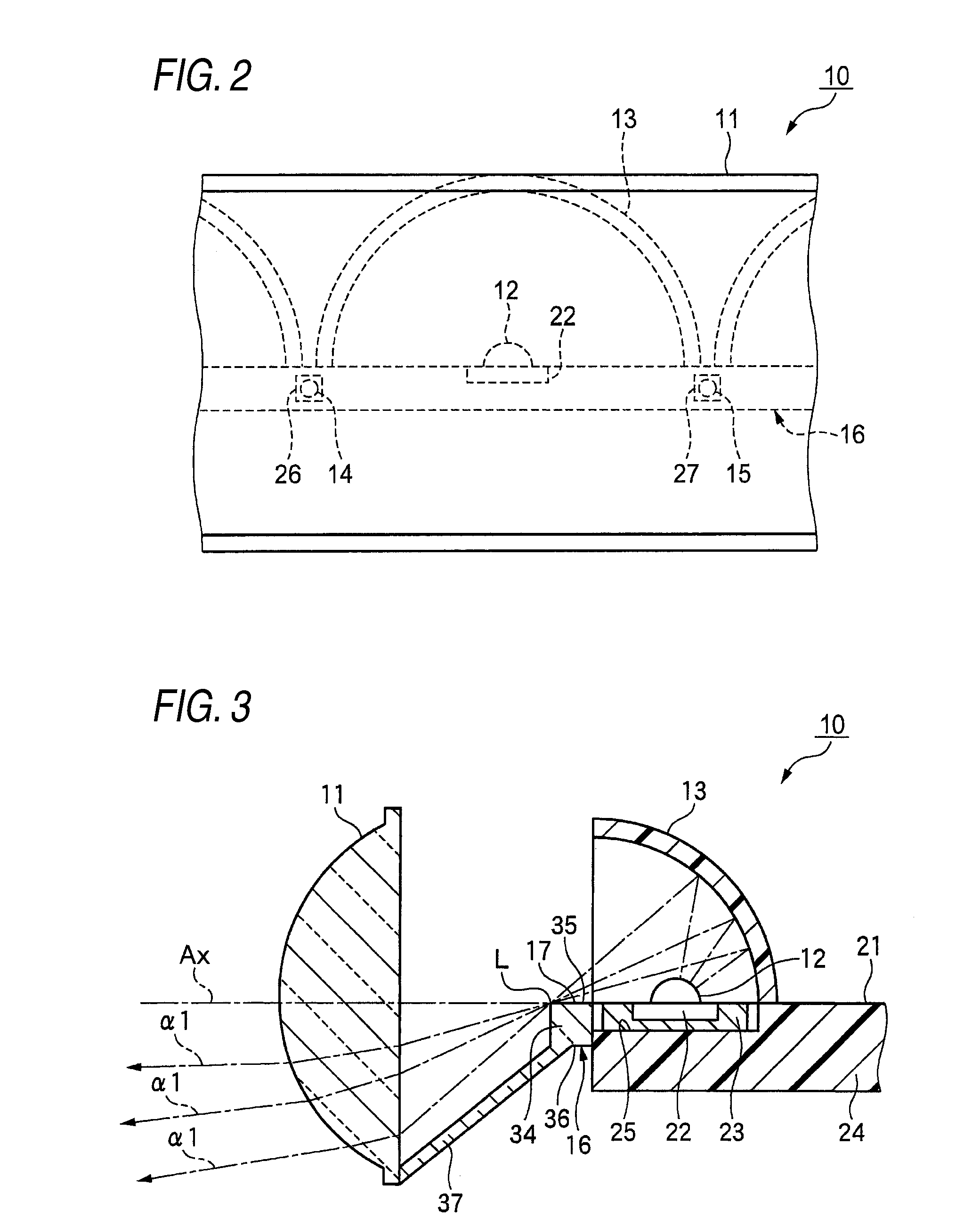
[0020]As shown in FIGS. 1 to 3, a lighting device 10 for a vehicle according to the first exemplary embodiment of the invention includes a projection lens 11 disposed on an optical axis Ax (see FIG. 3) which extends in a longitudinal direction of the vehicle. The projection lens 11 has a focal line L which extends in a lateral direction, and the projection lens 11 extends in a direction of the focal line L. The projection lens 11 is a cylindrical lens which is long in the lateral direction.

[0021]The lighting device 10 for a vehicle includes a first light emitting device 12 disposed on a rear side of the focal line L of the projection lens 11, and a reflector 13 for reflecting a light α1 emitted from the first light emitting device 12 toward the focal line L in a forward part. Moreover, the lighting device 10 for a vehicle includes a plurality of second light emitting devices 14 and 15 disposed on the rear side of the focal line L of the projection lens 11.

[0022]The lighting device 1...

second exemplary embodiment

[0042]Next, a lighting device for a vehicle according to a second exemplary embodiment of the invention will be described with reference to FIG. 5.

[0043]In the following second exemplary embodiment, the same components as those in the first exemplary embodiment have the same reference numerals and a description thereof will be omitted.

[0044]As shown in FIG. 5, a lighting device 40 for a vehicle according to the second exemplary embodiment of the invention includes a light guide 16 which divides a left light guide 41 disposed on a left side of a first light emitting device 12 and a right light guide 42 disposed on a right side of the first light emitting device 12 in FIG. 5. An independent shade portion 43 is disposed ahead of both of the light guides 41 and 42.

[0045]The lighting device 40 for a vehicle according to the second exemplary embodiment can produce the same functions and advantages as those in the first exemplary embodiment, and particularly, it is possible to simplify sha...


PUM


Abstract

A lighting device for a vehicle is provided. The lighting device includes a projection lens disposed on an optical axis and having a focal line, a first light emitting device disposed on a rear side of the focal line, a reflector which reflects light toward the focal line; a shade which shields a part of the light; a second light emitting device disposed on a rear side of the first light emitting device; and a light guide. The light guide includes an incident portion into which light emitted from the second light emitting device is introduced, a light guiding portion which guides the light, a shielding portion which forms a part of the shade, and an emitting portion coupled to the shielding portion and disposed on the focal line or in a vicinity of the focal line. The emitting portion emits the light guided by the light guiding portion.

Description

[0001]This application claims priority to Japanese Patent Application No. 2008-224657, filed Sep. 2, 2008, in the Japanese Patent Office. The Japanese Patent Application No. 2008-224657 is incorporated by reference in its entirety.TECHNICAL FIELD[0002]The present disclosure relates to a lighting device for a vehicle which includes a projection lens to be extended in a direction of a focal line.RELATED ART[0003]As an example of a related-art lighting device for a vehicle, JP-A-2007-213879 Publication describes a lighting device for a vehicle includes a first subunit and a second subunit. The first subunit is of a direct incident type for causing light emitted from a first light emitting device to be incident on a projection lens, and the second subunit is of an indirect incident type for reflecting a light emitted from a second light emitting device by a reflector and causing the reflected light to be incident on the projection lens. The first subunit and the second subunit are arran...

Claims


Application Information

Patent Timeline
IPC IPC(8): B60Q1/00
CPCF21S48/1154F21S48/1159F21S48/2225F21S48/215F21S48/1241F21S41/143F21S41/148F21S41/151F21S41/24F21S41/255F21S43/14F21S43/235
Inventor NAKABAYASHI, MASAAKI
Owner KOITO MFG CO LTD
Why Eureka
Try Eureka