Compression resistant floating hose for reeling applications

a compression-resistant, floating hose technology, applied in special-purpose vessels, liquid handling, closures using stoppers, etc., can solve the problems of floating hose damage, tack becomes even more difficult, and the propensity of floating hoses to lose buoyancy, so as to reduce the propensity of losing buoyancy

Inactive Publication Date: 2010-03-04
VEYANCE TECH
View PDF9 Cites 8 Cited by
  • Summary
  • Abstract
  • Description
  • Claims
  • Application Information

AI Technical Summary

Benefits of technology

[0008]The floating hose of this invention is resistant to damage that can be caused by axial and lateral forces, such as those encountered while being collected on a reel. More specifically the floating hose of this invention is not as susceptible to being damaged by compression as conventional floating hoses. This is by virtue of the floating hoses of this invention including anti-compression collars that protect the floatation medium therein from excessive compression that can occur during routine usage. This extends the service life of the floating hoses of this invention and reduces their propensity to lose buoyancy over time.

Problems solved by technology

However, transferring the crude oil from FPSOs to shuttle tankers at sea is an extremely demanding task because of the persisting relative movement between the vessels.
During times of adverse weather conditions, such as high waves, high winds, and storms at sea, this tack becomes even more difficult.
However, in such cases where the floating hose is left on the water the floating hose may be damaged by being struck by ships or by the shock from waves in stormy weather.
In any case, hose wear occurs due to continual wave action.
This can lead to a loss of the buoyancy and over time the hose can begin sink.
However, pulling the hose onto a reel is not a procedure that is free of problems.
For instance, the hose can be damaged by compression as it is pulled onto the reel and subsequently stored thereon.
This gives the hose virtually no time to recover from the compression under which it was subjected while being on the reel.
In any case, temporary and permanent compression damage causes the hose to loose buoyancy and can ultimately result in the hose sinking under conditions of normal use.

Method used


Image

  • Compression resistant floating hose for reeling applications
  • Compression resistant floating hose for reeling applications
  • Compression resistant floating hose for reeling applications

Examples


Embodiment Construction

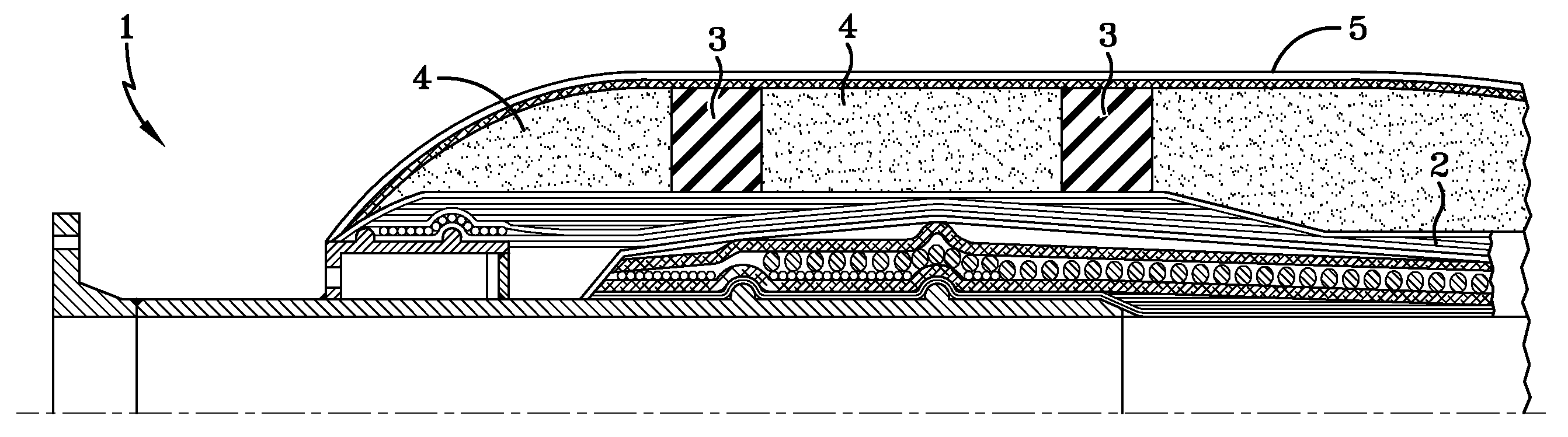
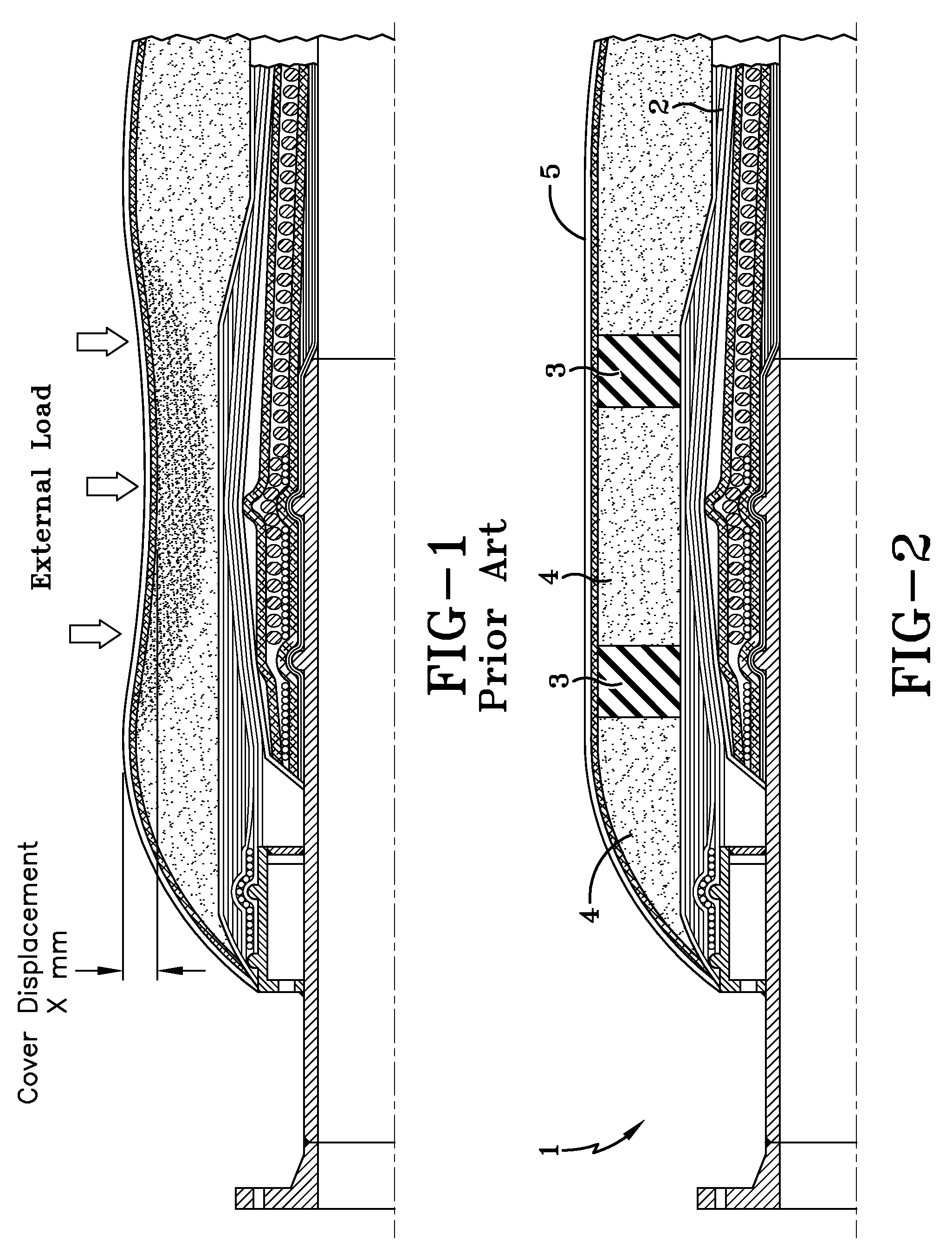
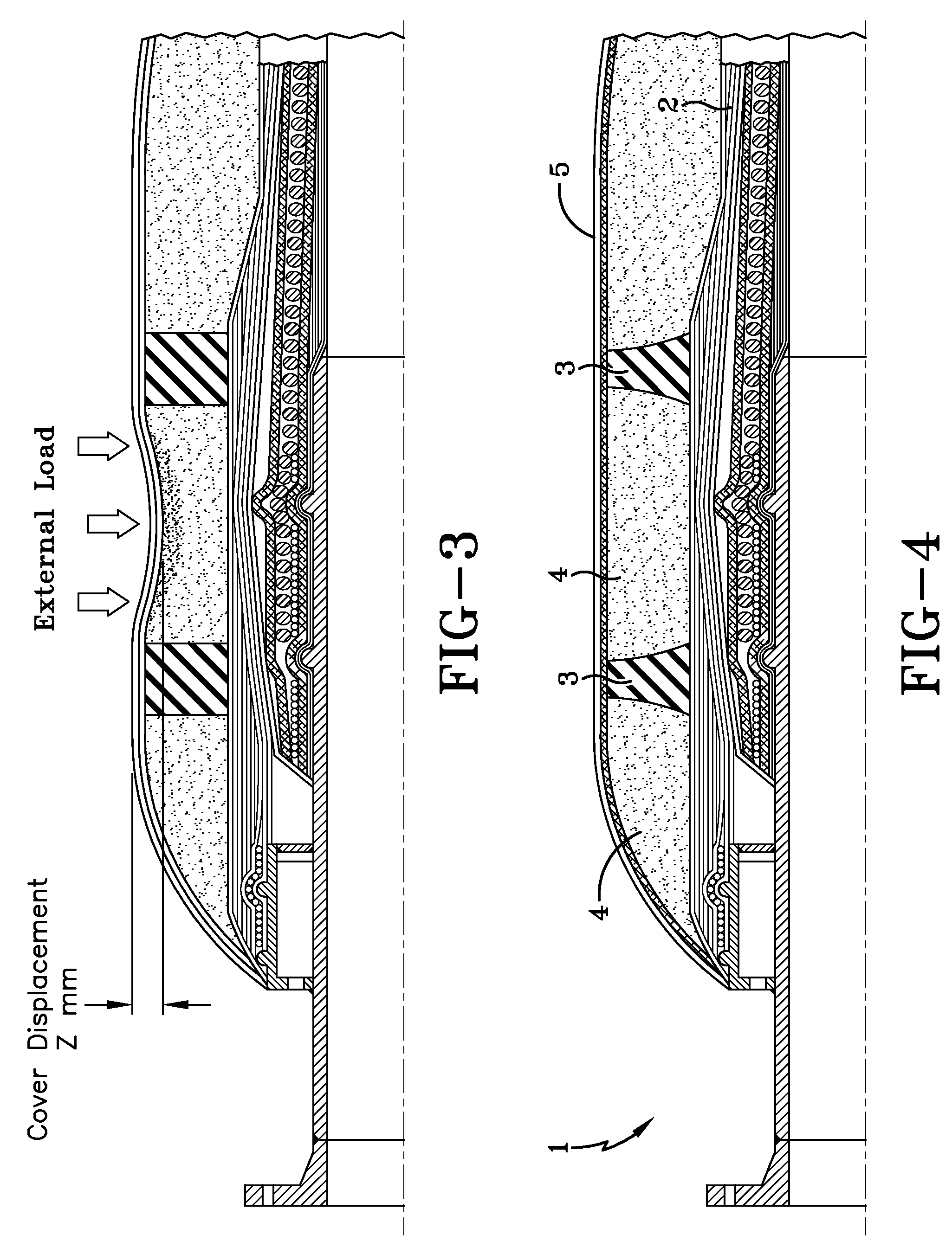
[0014]The floating hose 1 of the present invention as depicted in FIG. 1 includes a carcass 2 having an inside and an outside, a plurality of anti-compression collars 3 interspaced around the carcass, a floatation medium 4 surrounding the hose carcass and the anti-compression collars 3, and an outer cover 5. This type of floating hose typically has an inside diameter which is within the range of about 15 cm to 60 cm and an outside diameter which is within the range of about 25 cm to about 100 cm. It more typically has an inside diameter which is within the range of about 30 cm to 60 cm and an outside diameter which is within the range of about 40 cm to about 100 cm. For instance, many commercial floating hoses of this type have an inside diameter of 50 cm (20 inches) and an outside diameter of 95 cm (38 inches).

[0015]The carcass 2 is of a tubular shape and is typically comprised of a base submarine hose complete with end fittings. The hose carcass 2 is surrounded by a floatation med...


PUM

PropertyMeasurementUnit
lengthaaaaaaaaaa
lengthaaaaaaaaaa
internal diameteraaaaaaaaaa

Abstract

Floating hose is normally comprised of a carcass that is covered with a layer of foam to provide buoyancy. The foam can be deformed and compressed by being repeatedly reeled onto a drum under conditions of high axial forces (reeling forces plus hose weight). The propensity for the foam layer to become compressed is aggravated in typical conditions where the hose is stored on a reel for extended periods and is on the reel more than it is in the water. In any case, compression damage causes the hose to lose buoyancy which can ultimately result in the hose sinking under conditions of normal use. It would accordingly be desirable to develop a floating hose that minimized the permanent damage caused by the foam layer being compressed to high levels over and over again. The floating hose of this invention is resistant to damage that can be caused by axial forces, such as those encountered while being collected on a reel. More specifically, the floating hose of this invention is not as susceptible to being damaged by compression as conventional floating hoses. This is by virtue of the floating hoses of this invention including anti-compression collars that protect the floatation medium therein from damage that can occur during routine usage. This extends the service life of the floating hoses of this invention and reduces their propensity to lose buoyancy over time. The present invention more specifically discloses a floating hose comprising: a carcass having an inside and an outside; a plurality of anti-compression collars interspaced around the carcass; a floatation medium surrounding said hose carcass and said anti-compression collars, and an outer cover, wherein said outer cover covers said floating medium and said anti-compression collars.

Description

[0001]This application claims benefit of U.S. Provisional Patent Application Ser. No. 61 / 094,153, filed on Sep. 4, 2008. The teachings of U.S. Provisional Patent Application Ser. No. 61 / 094,153 are incorporated herein by reference in their entirety.BACKGROUND OF THE INVENTION[0002]The production of petroleum from off-shore locations is of growing importance in the world today. This is because vast reserves of petroleum are located under water in many locations around the world including under the North Sea, the Gulf of Mexico, off the coast of Brazil, and off the coast of California. Floating Production Storage and Offloading units (FPSOs) are typically used in the recovery of such petroleum reserves that are located under water. The FPSO may draw oil from a number of oil wells that have been drilled under water.[0003]After being pumped the crude petroleum is temporarily stored in the FPSO. Then the crude petroleum is transferred to a shuttle tanker for delivery to a desired locatio...

Claims


Application Information

Patent Timeline
Patent Type & Authority Applications(United States)
IPC IPC(8): B32B1/08B32B37/00
CPCF16L11/133Y10T428/1376B63B22/021
Inventor CHEVALIER, RONALD M.BOLONHEZI, MAURICIODE LUCENA, WALDIR PERIERA
Owner VEYANCE TECH
Why Eureka
Try Eureka