Articulated bench

a technology of articulating benches and supporting legs, which is applied in the field of supporting benches, can solve the problems of compromising the utility of wolff, christie, larossa et al. devices for non-weightlifting purposes, and the collapse of the massaging table of lloyd, and achieves the effects of reducing manufacturing costs, providing durability and portability, and economic manufacturing

Inactive Publication Date: 2004-10-19
PARKER JAMES
View PDF13 Cites 53 Cited by
  • Summary
  • Abstract
  • Description
  • Claims
  • Application Information

AI Technical Summary

Benefits of technology

A support leg assembly is pivotally mounted at each end of the rectangular frame. The support leg assemblies fold inward for storing or transporting the bench. Upon folding outward, a locking folding brace holds the legs in position substantially perpendicular to the frame. The support leg assemblies pivot about axles that are common to the U-shaped support assemblies, and the common axes increase'stability and reduce manufacturing costs.
The articulated bench of the present invention is fabricated of a variety of strong, light-weight materials to provide the durability and portability required by the nature of its usage. The present invention's design is simple and straightforward, and can be economically manufactured.

Problems solved by technology

Unfortunately, each of these prior art devices possesses a design specific to use either for massage or weightlifting purposes.
The massage table of Lloyd, while collapsible, does not provide the upper / lower body support in an inclined position required by weightlifting or other exercise programs.
The utility of the Wolff, Christie, and LaRossa et al. devices for non-weightlifting purposes is compromised by the presence of barbell support posts.

Method used


Image

  • Articulated bench
  • Articulated bench
  • Articulated bench

Examples


Embodiment Construction

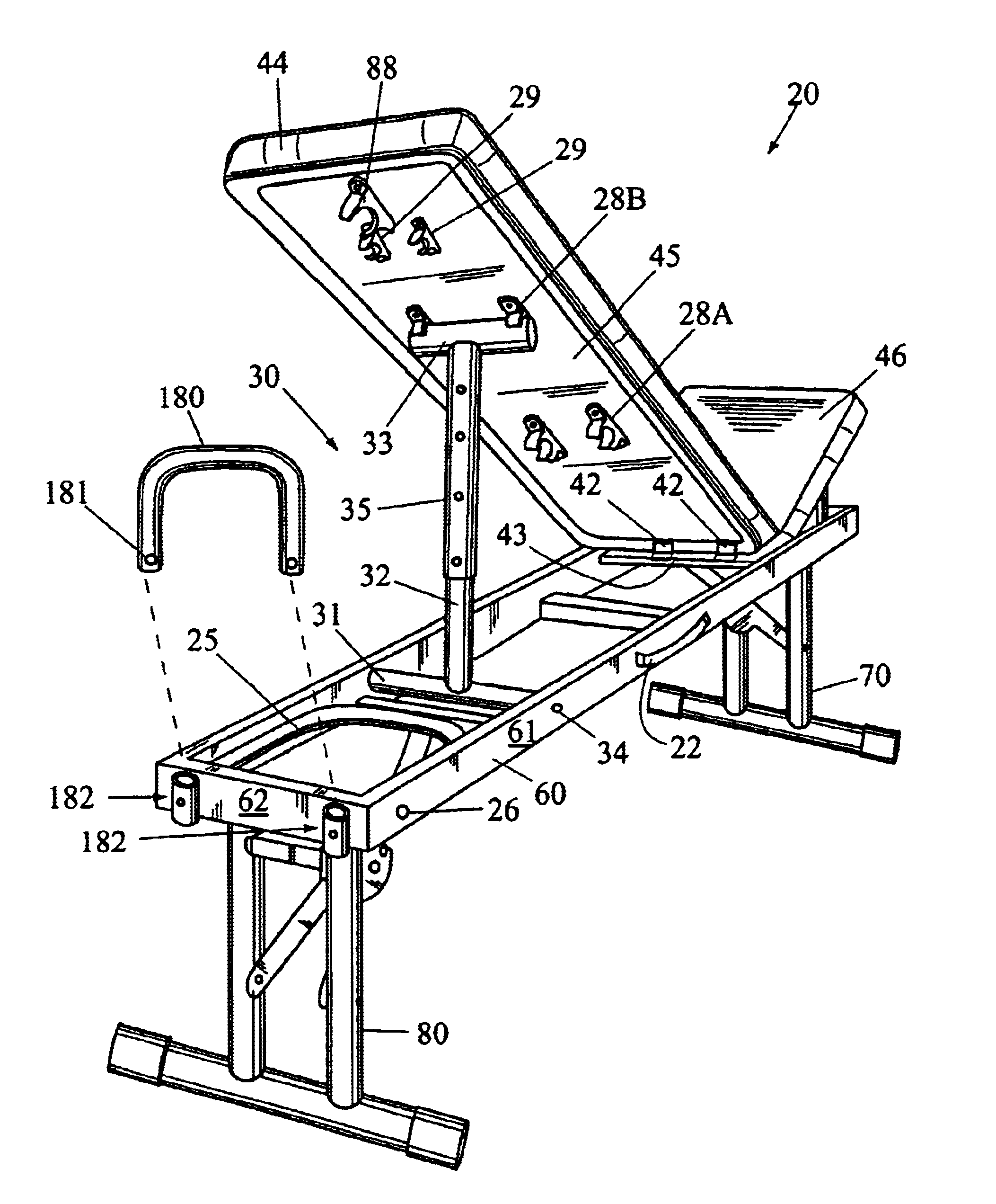
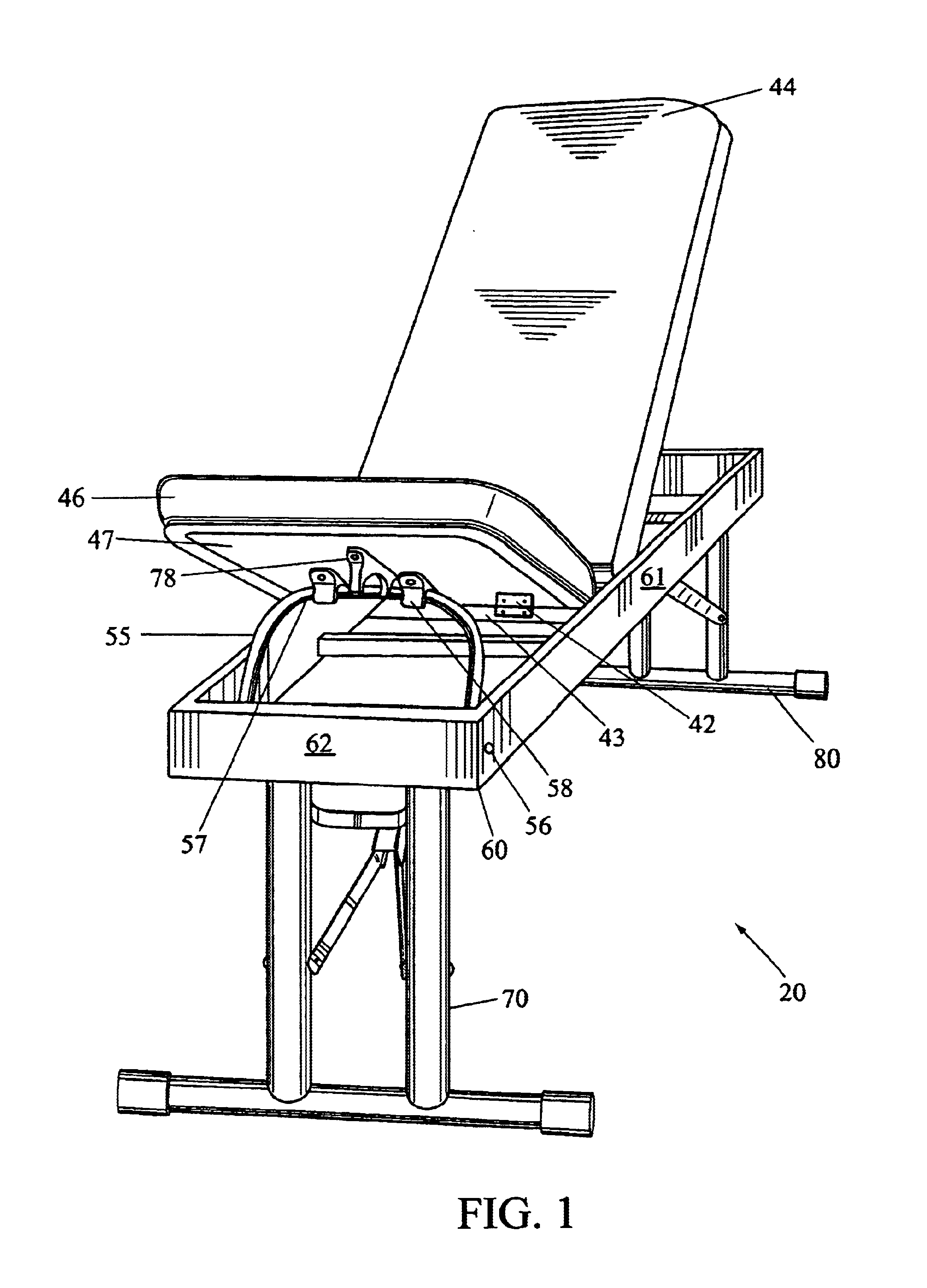
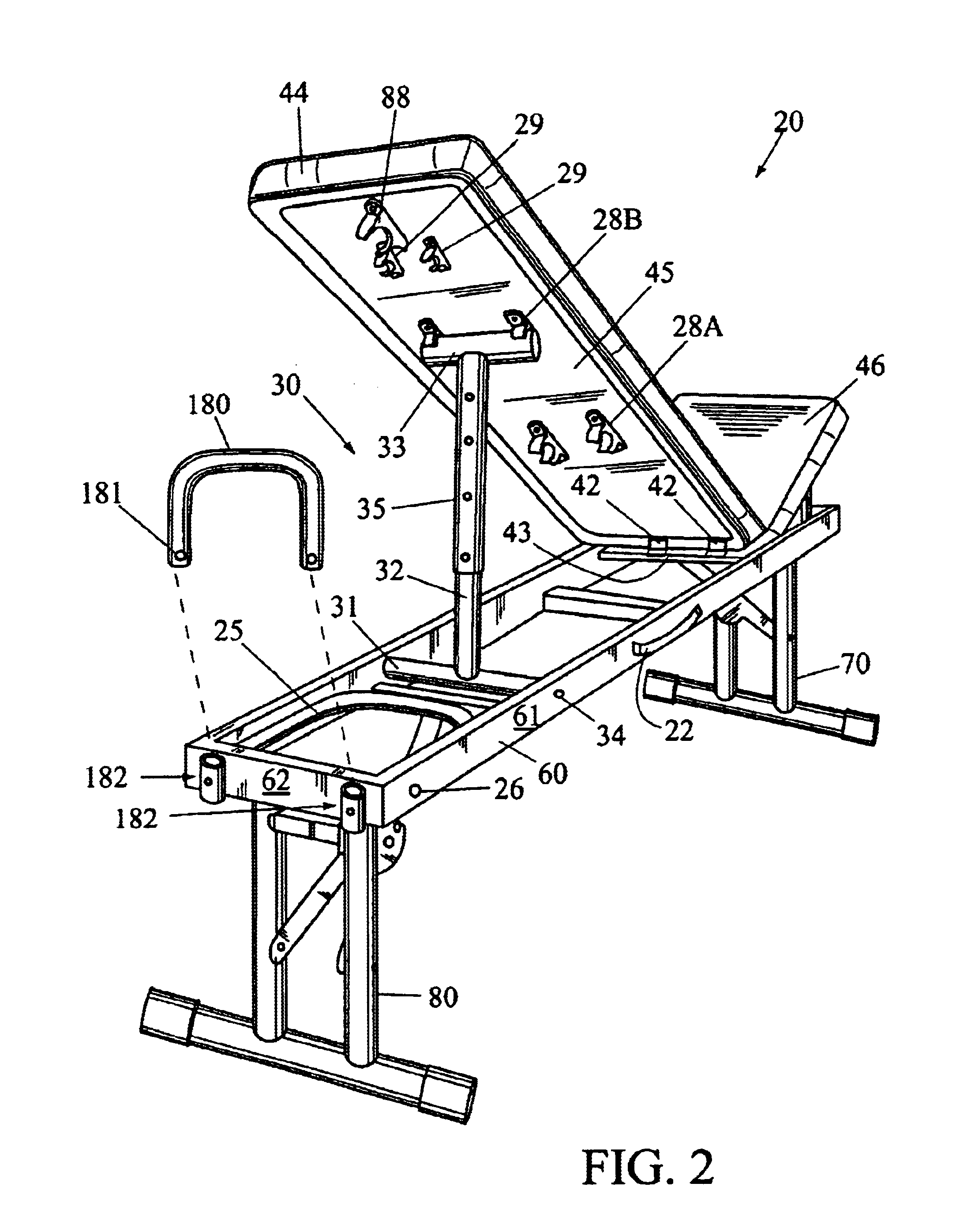
FIGS. 1-2 are, respectively, front and rear perspective views of an articulated bench 20 according to a first embodiment of the present invention.

The articulated bench 20 according to the present invention generally comprises a two-section supporting surface comprising two articulated padded sections 44, 46 that are pivotally attached by a plurality of hinges 42 to a fixed strut 43 (see FIG. 2) that spans the rectangular frame 60. One skilled in the art should appreciate that a middle padded section can be included between the two articulated padded sections 44, 46 to introduce a space there between if so desired. In this case two separate hinges would be required, one for each pivotally-coupled padded section 44, 46. In addition, the frame 60 may be other than rectangular, for instance, with rounded corners, without departing from the scope and spirit of the invention.

In addition, two folding / pivoting support leg assemblies 70, 80 are pivot downward from the frame 60. A handle 22 (...


PUM


Abstract

An articulated bench comprising a two-section pad attached to a rectangular frame and two folding/pivoting support leg assemblies. The two padded sections are pivotally attached to the frame. Either of the two padded end sections can be pivoted upward and locked at a selectable incline. Either of a length-adjustable I-shaped brace assembly, or alternatively, a U-shaped support assembly fold out of the frame from beneath the longer of the two pivoting, padded end sections (i.e. the section for supporting the upper body) and are inserted into one of a series of catches located on the section's rear surface to hold it at a selectable incline. The shorter of the two pivoting, padded end sections (i.e. the section for supporting an individual's lower body) also pivots upward and a U-shaped support assembly folds out of the frame and is inserted in a pair of surface-mounted catches to maintain the section in an inclined position. The present invention's design is simple and straightforward, and can be economically manufactured and can quickly and easily be set up, or knocked down and carried.

Description

BACKGROUND OF THE INVENTION1. Field of the InventionThe present invention relates to support benches such as utilized during body toning, weight training, and other therapeutic activities and, more particularly, to a portable, fully-articulated, multi-purpose bench.2. Description of the BackgroundMany different activities such as body toning, weight training, weight-lifting, and other therapeutic and / or athletic activities require the use of a supporting structure capable of supporting the body in a variety of positions. For example, for an effective workout a weight lifter must exercise all major muscle groups by placing themself in a variety of positions ranging from flat-on-their-stomach, to reclining, to flat-on-their back, and all at a height that provides a full range of arm or leg motion. Similarly, many body toning exercises, aerobic programs, rehabilitative, and like therapeutic activities require the participant to position himself / herself in a variety of seated or lying p...

Claims


Application Information

Patent Timeline
Patent Type & Authority Patents(United States)
IPC IPC(8): A47C9/00A63B21/078A63B21/06A63B23/00
CPCA47C9/002A63B21/1457A63B21/078A63B21/00047A63B21/4029
Inventor PARKER, JAMES
Owner PARKER JAMES
Why Eureka
Try Eureka