System and method for direct injection of gaseous fuel into internal combustion engine

a gaseous fuel and internal combustion engine technology, applied in the direction of machines/engines, output power, electric control, etc., can solve the problems of reducing volumetric efficiency by a factor of up to thirty percent, reducing torque and maximum power, and prone to pre-ignition and further reduction of engine output, so as to reduce the effect of exhaust emissions

Inactive Publication Date: 2006-10-10
FORD GLOBAL TECH LLC
View PDF11 Cites 53 Cited by
  • Summary
  • Abstract
  • Description
  • Claims
  • Application Information

AI Technical Summary

Benefits of technology

[0002]An engine may burn gaseous fuels such as hydrogen (H2), natural gas, lighter flammable hydrocarbon derivatives, etc. Using gaseous fuel in an internal combustion engine can provide various advantages compared to liquid fuel injection, such as reduction of exhaust emissions of nitrogen oxides, particulate matter, and hydrocarbons.

Problems solved by technology

This method may result in reduced volumetric efficiency by a factor of up to thirty percent at stoichiometry due to the displacement of air by the gaseous H2, and a consequent loss in torque and maximum power.
Also in these systems, the H2 may be exposed to hot residual gases as well as heated intake manifold and cylinder head porting and cylinder walls during the intake stroke, which can causes a propensity to pre-ignition and further reduction in engine output.
However, the inventors herein have recognized several disadvantages of such an approach.
Thus, the injected gaseous fuel may undergo a sudden expansion and result in flow losses upon entering the combustion chamber.
Further, because cylinder pressure may be reduced during the first part of the intake stroke (before the intake valve is opened), increased pumping work may result.
Consequently, any injection energy of the gaseous fuel may not be efficiently utilized.
Moreover, a propensity to pre-ignition may still exist at increased load conditions.
Further, the combination of early exhaust valve closure and late intake valve opening can have only a small overall effect on the pumping work.

Method used


Image

  • System and method for direct injection of gaseous fuel into internal combustion engine
  • System and method for direct injection of gaseous fuel into internal combustion engine
  • System and method for direct injection of gaseous fuel into internal combustion engine

Examples


Embodiment Construction

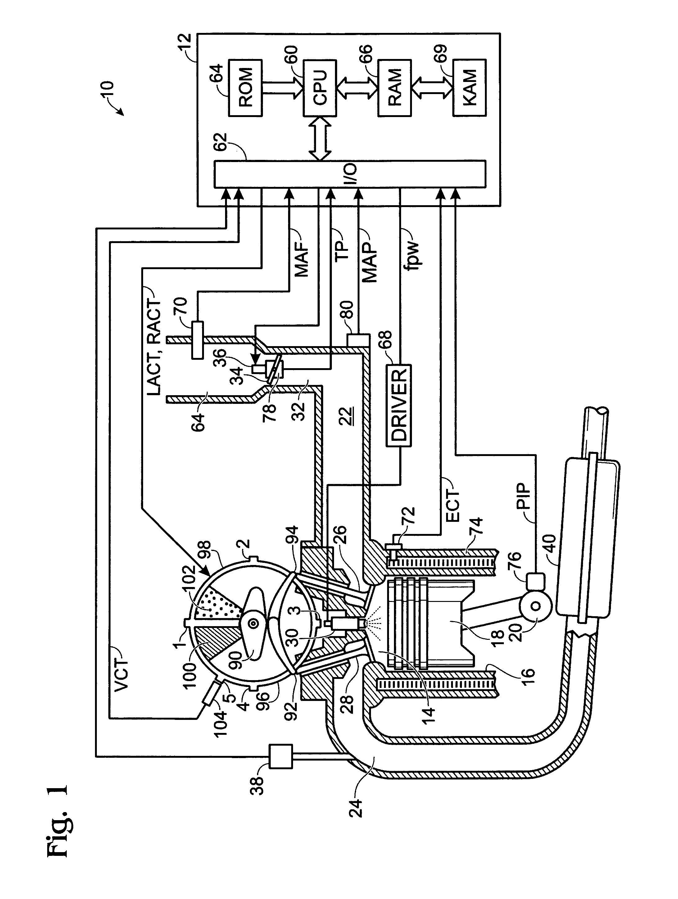
[0019]FIG. 1 shows, generally at 10, an exemplary embodiment of one cylinder of a multi-cylinder engine, intake and exhaust paths connected to that cylinder, and an exemplary embodiment of a camshaft having a variable timing mechanism for controlling the valves of the cylinder. It will be appreciated that the configuration of engine 10 is merely exemplary, and that the systems and methods described herein may be implemented in any other suitable engine. Further, the engine may be spark ignited via a spark plug located in the cylinder (not shown), the timing of which may be varied with operating conditions.

[0020]Continuing with FIG. 1, engine 10 is controlled by electronic engine controller 12. Combustion chamber, or cylinder, 14 of engine 10 is shown including combustion chamber walls 16 with piston 18 positioned therein and connected to crankshaft 20. Combustion chamber 14 is shown communicating with intake manifold 22 and exhaust manifold 24 past intake valve 26 and exhaust valve ...


PUM


Abstract

A method for an engine capable of burning gaseous fuel, the engine also including a combustion chamber, at least one intake valve, and at least one exhaust valve, an injector to directly inject pressurized gaseous fuel into the combustion chamber, and a variable valve timing system coupled to the intake valves and exhaust valves, the method comprising closing the exhaust valve before top dead center of piston position to increase combustion chamber pressure achieved at top dead center and to trap exhaust gas in the cylinder; and starting injection of a gaseous fuel directly into the combustion chamber after the exhaust valve is closed and before the intake valve is opened.

Description

FIELD[0001]The present application relates generally to a system and method for direct injection of gaseous fuel, such as hydrogen, into an internal combustion engine, and more specifically to a system and method that utilizes cylinder negative valve overlap of intake and exhaust valves for improving engine efficiency.BACKGROUND AND SUMMARY[0002]An engine may burn gaseous fuels such as hydrogen (H2), natural gas, lighter flammable hydrocarbon derivatives, etc. Using gaseous fuel in an internal combustion engine can provide various advantages compared to liquid fuel injection, such as reduction of exhaust emissions of nitrogen oxides, particulate matter, and hydrocarbons.[0003]In one approach, a pre-mixed approach (or external mixture formation), which may include port injection, is used to induct gaseous H2. This method may result in reduced volumetric efficiency by a factor of up to thirty percent at stoichiometry due to the displacement of air by the gaseous H2, and a consequent l...

Claims


Application Information

Patent Timeline
Patent Type & Authority Patents(United States)
IPC IPC(8): F01L1/34F02B17/00
CPCF02D13/0219F02D13/0265F02D35/023F02D41/0027F02D41/401F02M25/0752F02M21/0275F02D19/022F02D19/024F01L2800/00Y02T10/36F02D2041/001F02D2200/0406F02D2200/0602Y02T10/44Y02T10/123Y02T10/32F02M21/0206Y02T10/18F02B2075/125F02M26/01Y02T10/12Y02T10/30Y02T10/40
Inventor BOYER, BRADSTOCKHAUSEN, WILLIAM
Owner FORD GLOBAL TECH LLC
Why Eureka
Try Eureka