
Wireless communication device

a communication device and wireless technology, applied in the direction of instruments, electric signalling details, signalling systems, etc., can solve problems such as the possibility of communication interruption

Inactive Publication Date: 2010-03-04
KK TOSHIBA
View PDF5 Cites 6 Cited by
  • Summary
  • Abstract
  • Description
  • Claims
  • Application Information

AI Technical Summary

Problems solved by technology

For making communication via such close proximity wireless transfer system, there is a possibility of interruption of communication if users move their terminal devices accidentally.

Method used


Image

  • Wireless communication device
  • Wireless communication device
  • Wireless communication device

Examples


first embodiment

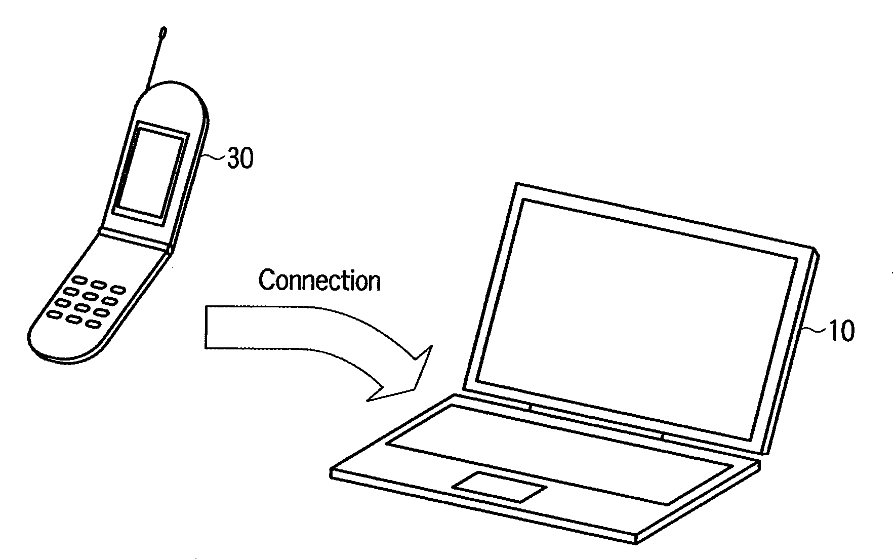
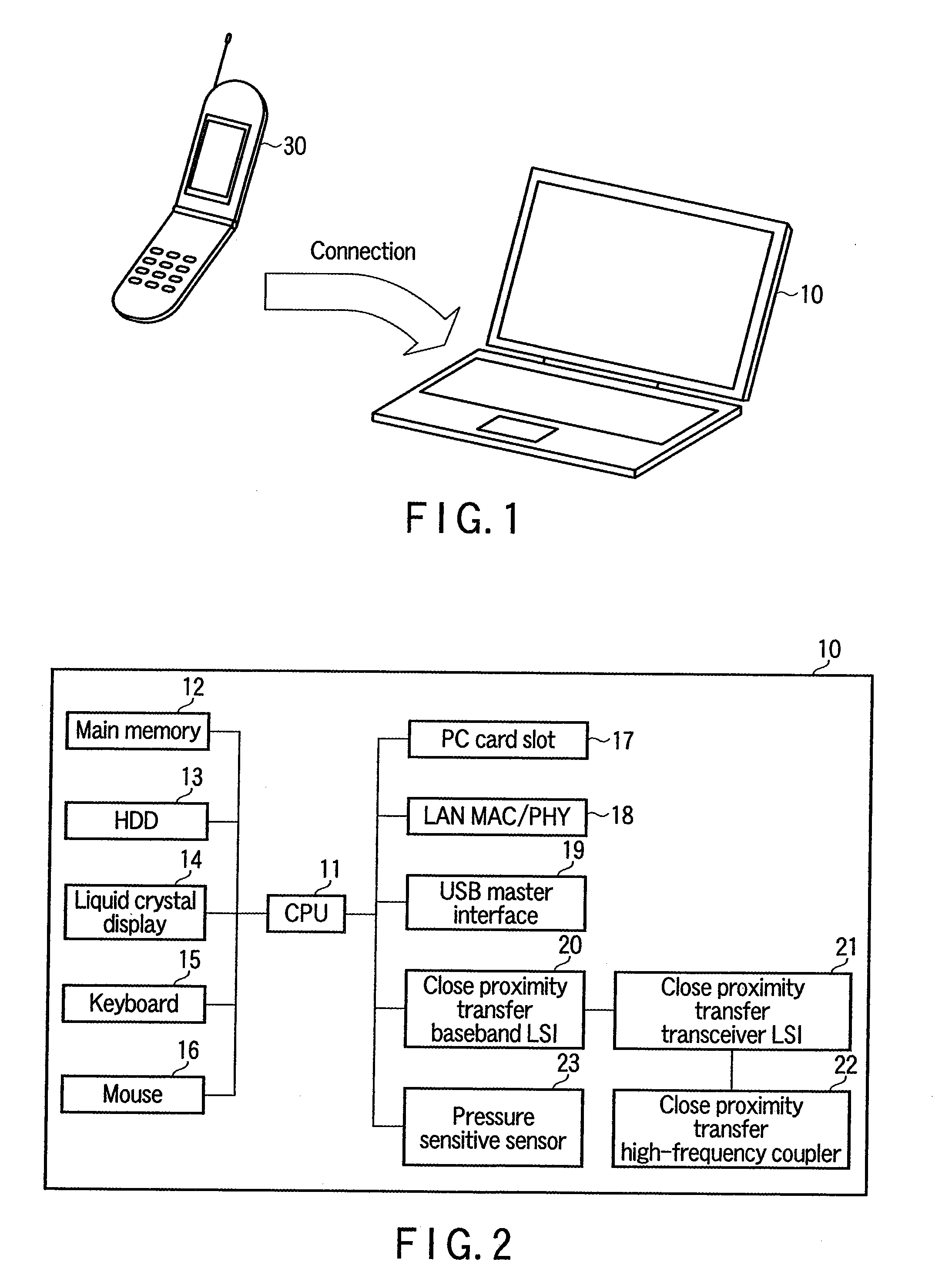
[0028]FIG. 1 shows a perspective view illustrating an exterior appearance of a notebook personal computer 10 and a cellular phone 30 as wireless communication devices of a first embodiment of the invention.

[0029]The computer 10 and the cellular phone 30 execute close proximity wireless transfer. The close proximity wireless transfer between the computer 10 and the cellular phone 30 is executed in a peer-to-peer form. A communication distance is, for example, 3 cm. A wireless connection between the computer 10 and a cellular phone 30 is enabled only when the distance between the computer 10 and the cellular phone 30 is within the communication distance (e.g., 3 cm). When the computer 10 and the cellular phone 30 are within the communicable distance, the connection between the computer 10 and the cellular phone 30 is effected. A data transfer of a data file expressly specified by a user, or a preset synchronization object data file are executed between the computer 10 and the cellular...

second embodiment

[0118]While the first embodiment has described the case in which the pressure sensitive sensor is disposed on a device side to receive the data, an example of a second embodiment in which the pressure sensitive sensor is disposed on a device side to transmit the data will be described hereinafter.

[0119]FIG. 14 shows a block diagram illustrating a system configuration of the personal computer 10 regarding the second embodiment of the invention.

[0120]As shown in FIG. 14, the computer 10 includes the CPU 11, main memory 12, HDD 13, liquid crystal display 14, keyboard 15, mouse 16, PC card slot 17, LAN MAC / PHY 18, USB master interface 19, close proximity wireless transfer baseband LSI 20, close proximity wireless transfer transceiver LSI 21, and close proximity wireless transfer radio-frequency coupler 22. The same components as those of FIG. 2 are designated by identical symbols and the description thereof will be omitted.

[0121]FIG. 15 shows a view illustrating an example of the system...


PUM


Abstract

According to one embodiment, a wireless communication device includes a housing provided with a first face, a radio-frequency coupler installed in the housing so as to face the first face, a close proximity wireless transfer device configured to execute close proximity wireless transfer with the external device existing within a prescribed wirelessly communicable distance from the radio-frequency coupler, a pressure sensitive sensor configured to measure the pressure applied to the first face near the radio-frequency coupler, a reception data processor configured to process data received by the radio-frequency coupler and the close proximity wireless transfer device, and a controller configured to report to the reception data processor that close proximity wireless transfer is available when the close proximity wireless transfer is available and also a measured value of the pressure sensitive sensor is not smaller than a threshold value.

Description

CROSS-REFERENCE TO RELATED APPLICATIONS[0001]This application is based upon and claims the benefit of priority from Japanese Patent Application No. 2008-221473, filed Aug. 29, 2008, the entire contents of which are incorporated herein by reference.BACKGROUND[0002]1. Field[0003]One embodiment of the invention relates to a wireless communication device which performs close proximity wireless transfer.[0004]2. Description of the Related Art[0005]A close proximity wireless transfer system may communicate among devices when users bring their devices near to each other. Since these operations are intuitive and simple for the users, close proximity wireless transfer is expected to be used widely for cellular phone terminals (See Jpn. Pat. Appln. KOKAI Publication No. 2008-99236).[0006]For making communication via such close proximity wireless transfer system, there is a possibility of interruption of communication if users move their terminal devices accidentally. Or, there may be a possib...

Claims


Application Information

Patent Timeline
Patent Type & Authority Applications(United States)
IPC IPC(8): H04B5/00
CPCH04M1/7253H04M2250/64H04M2250/12H04M1/72412
Inventor TOMODA, ICHIRO
Owner KK TOSHIBA
Learn More