Limited slip differential

a technology of differential and slip differential, applied in the field of differentials, can solve the problems of complex structure and rendering the vehicle inability to formally operate, and achieve the effects of reducing costs, convenient installation and maintenance, and efficient adjustment of rotational speed differences

Inactive Publication Date: 2010-03-04
LEE KUO MING +1
View PDF7 Cites 7 Cited by
  • Summary
  • Abstract
  • Description
  • Claims
  • Application Information

AI Technical Summary

Benefits of technology

[0005]The objective of the present invention is to offer a limited slip differential benefiting a convenient installation and maintenance without complicate parts for decreasing costs, efficiently adjusting a rotational speed difference, and attaining a limited-slip effect.
[0006]The limited slip differential adapted to a vehicle in accordance with the present invention mainly comprises a sealed differential casing containing fluid, a driving plate disposed in the accommodating space, two backing plates pivotally connected with both sides of the driving plate, a plurality of differential gear assemblies disposed on the driving plate and a transmission assembly synchronized with the gear assemblies. Wherein, the driving plate includes a plurality pairs of openings and each pair is in communication, so that two differential gears of each gear assembly would interlock and rotatively mesh with each other. The two gears respectively penetrate through the correspondent openings and holes for separately engaging with two planetary gears and sun gears of the transmission assembly; each backing plate further provides holes disposed relatively to the above openings for traveling the fluid through the interstices between the two differential gears. Each sun gear includes an axis oppositely pivoted to the driving plate and extended to an axle shaft of the vehicle. Accordingly, the present invention needs not complicated components for attaining a convenient assemblage and maintenance. Moreover, when the vehicle simultaneously drives the transmission assembly along with the above plates, the differential gear assemblies are triggered to promote a mutual rotating relationship so as to adjust the rotational speed of the axle shafts. In the event that a rotational speed difference between the axes of the sun gears driven by the vehicle exceeds a predetermined threshold, at least one differential gear assembly immediately delivers a back pressure to avoid seeping the fluid between the two differential gears, and then the two meshed gears would stop rotating to prevent from enlarging the rotational speed difference. Thus, the LSD efficiently benefits a limited-slip effect as well.

Problems solved by technology

Once the vehicle is driven on a humid or greasy road to cause the wheel slipped or soared, the slipped wheel idly rotates and the other wheel loses the supported dynamic torque imparted from the vehicle as well, thence rendering the vehicle unable to formally operate.
Whereas, deficiencies attendant on the differentials are complex structures, an uneasy repairing and maintenance, and an effective operation under a large speed difference.

Method used


Image

  • Limited slip differential
  • Limited slip differential
  • Limited slip differential

Examples


Embodiment Construction

[0019]Before describing in details, it should note the like elements are denoted by similar reference numerals throughout the disclosure.

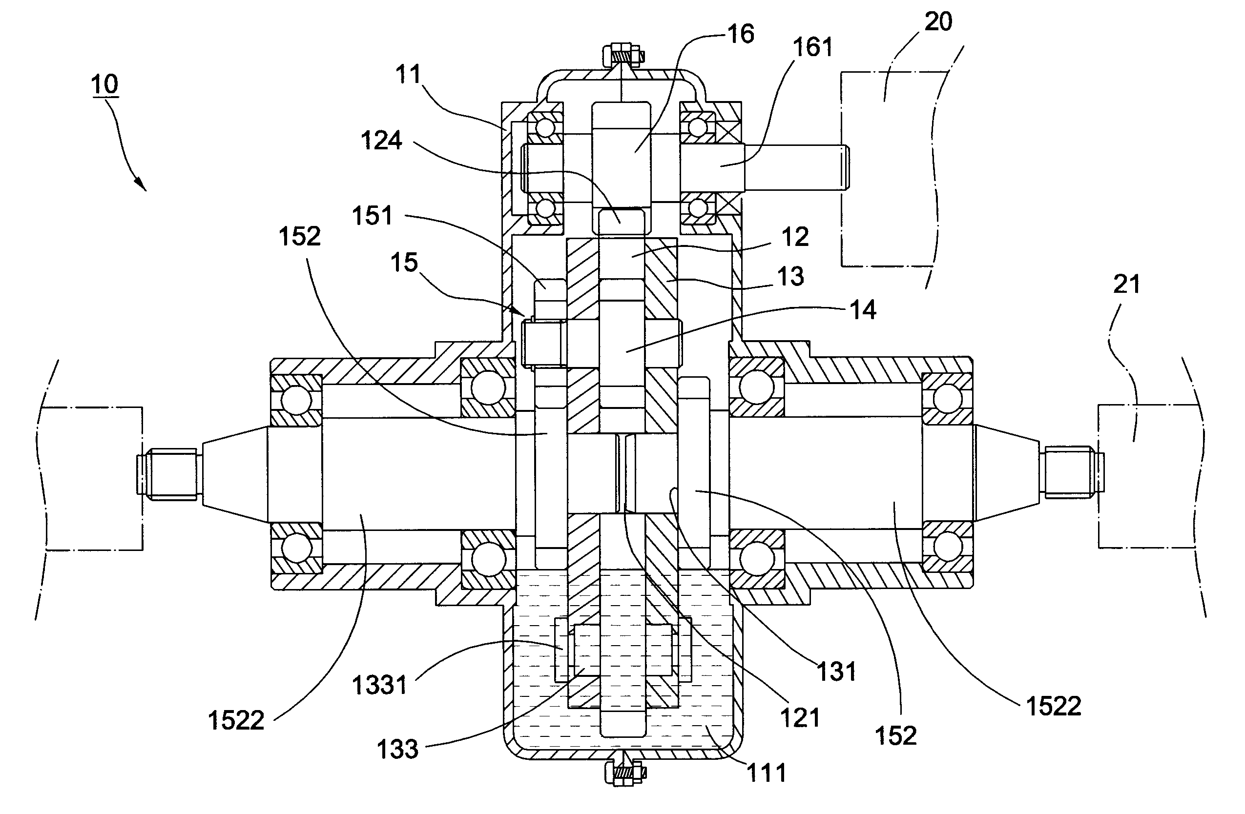
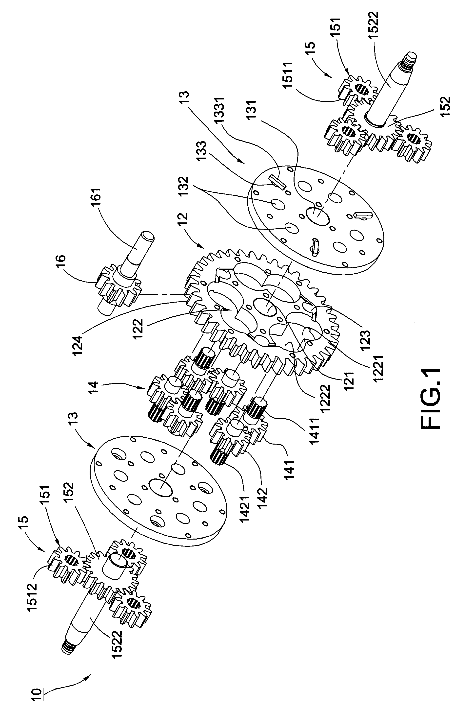
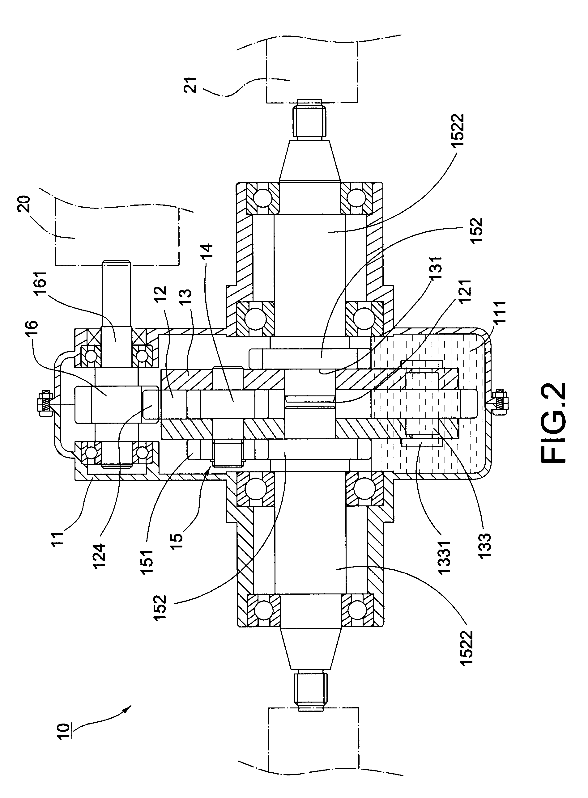
[0020]Referring to FIGS. 1 and 2 shows a limited slip differential (LSD) 10 of the first preferred embodiment adapted to a vehicle (not shown) comprising a differential casing 11, a driving plate 12 disposed within the differential casing 11, two backing plates 13 respectively attached to both sides of the driving plate 12, a plurality of differential gear assemblies 14 mounted on the driving plate 12, and a transmission assembly 15 engaged and synchronized with the differential gear assemblies 14. Wherein, the differential casing 11 is interlocked to form a sealed room, in which a shared accommodating space 111 is defined to contain fluid. Further, the driving plate 12 is placed within the accommodating space 111 for partially soaking in the fluid, which further includes an inserting bore 121 and pairs of openings 122 substantially disposed around...


PUM


Abstract

A limited slip differential includes a driving plate, backing plates, differential gear assemblies, and a transmission assembly engaged together inside a sealed casing where fluid is pumped. The driving plate has pairs of communicated openings for interlocking two gears of each gear assembly, which extend by opposite directions from the driving plate for separately engaging with the transmission assembly. While synchronously rotating the plates, the gear assemblies are alternatively soaked into the fluid and each permits the fluid passing among the gears for adjusting the rotational speed. In the event that the rotational speed difference of axle shafts of the vehicle exceeds a threshold value, the LSD applies at least one gear assembly to generate a back pressure and efficiently block the fluid passing through the gears for limiting mutual rotational speed difference, hence achieving a limited-slip effect.

Description

BACKGROUND OF THE INVENTION[0001]1. Field of the Invention[0002]The present invention relates to differentials, particularly to a limited slip differential applied to a vehicle.[0003]2. Description of the Related Art[0004]Differentials are well-known mechanisms and comprised of means to adequately transfer rotational torque when there are differences on rotational speeds between the opposite output axle shafts of wheels on the vehicle. A conventional mechanical differential includes two planetary gears meshing with side gears on two output shafts, whereby the planetary gears are significantly driven according to the different rotational speed between the side gears. When the wheels rotate on different road engagements to produce different rotational speed, the conventional differential is passively triggered without restricting rotations of the two axle shafts. Once the vehicle is driven on a humid or greasy road to cause the wheel slipped or soared, the slipped wheel idly rotates a...

Claims


Application Information

Patent Timeline
IPC IPC(8): F16H48/26F16H48/06F16H48/20F16H48/10F16H48/11F16H48/27F16H48/38F16H48/40F16H57/037F16H57/038F16H57/039F16H57/04
CPCF16H48/10F16H48/11F16H48/26F16H2200/2071F16H48/32F16H2048/423F16H2048/426F16H48/27
Inventor LEE, KUO-MINGHSIEH, YU-AN
Owner LEE KUO MING
Why Eureka
Try Eureka