
Emission sensor device and bioinformation detecting method

a technology of emission sensor and bioinformation, which is applied in the direction of instruments, catheters, applications, etc., can solve the problems of increasing the size of the apparatus and the difficulty of making a measurement at the same site, and achieve the effect of convenient application and extremely accurate detection of biological information

Inactive Publication Date: 2010-03-04
PIONEER CORP +1
View PDF9 Cites 46 Cited by
  • Summary
  • Abstract
  • Description
  • Claims
  • Application Information

AI Technical Summary

Benefits of technology

The present invention provides a light-emitting sensor apparatus and a detection method that can be miniaturized and can accurately detect a predetermined type of information on a measured sample, such as biological information. The apparatus includes a substrate, an applying device, and a light receiving device. The applying device applies a plurality of light with different wavelengths to the measured sample, and the light receiving device detects the light caused by the applied light. The plurality of light is applied to the same site on the measured sample, and the layout area is significantly reduced. This facilitates the miniaturization of the apparatus and the application of the light to the same site on the measured sample. The light from the measured sample is detected by the light receiving device, which can also derive new information by comparing information obtained by emitting light with different wavelengths. The applying device and the light receiving device are arranged on the same substrate, which further reduces the layout area.

Problems solved by technology

However, according to the technology as described above, in order to make a measurement by the light with the different wavelengths, at least two laser elements are to be provided, and this causes an increase in size of the apparatus, which is technically problematic.
Moreover, since the laser beams with the different wavelengths are emitted from different places, it is extremely hard to make a measurement at the same site, which is also technically problematic.

Method used


Image

  • Emission sensor device and bioinformation detecting method
  • Emission sensor device and bioinformation detecting method
  • Emission sensor device and bioinformation detecting method

Examples


first embodiment

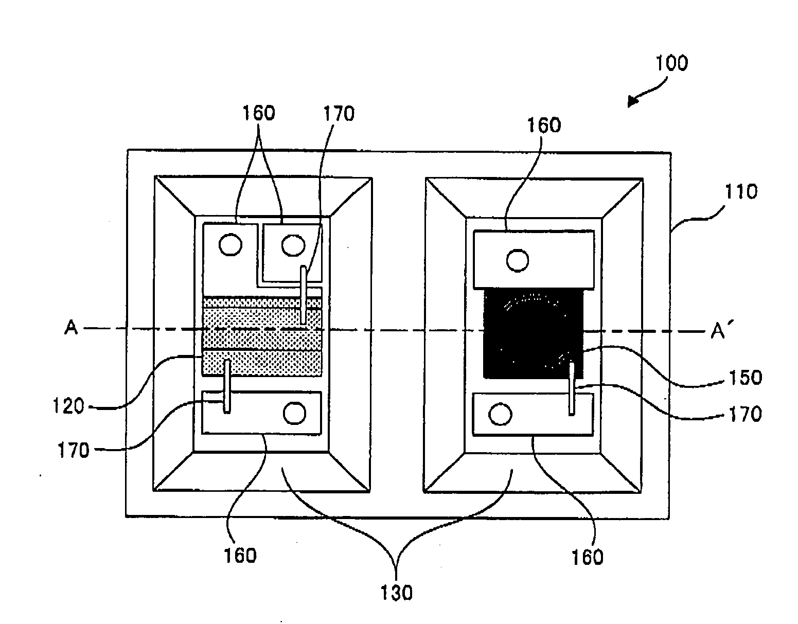
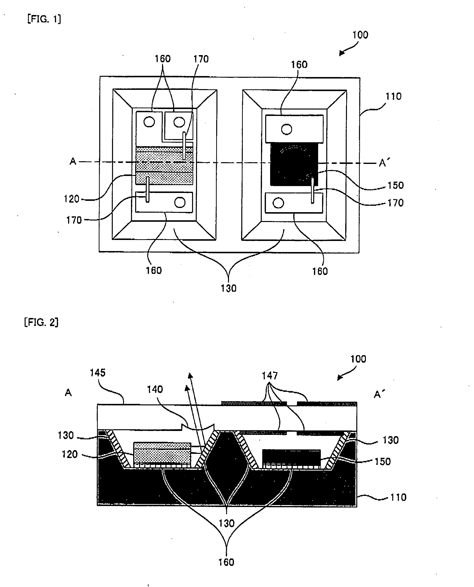
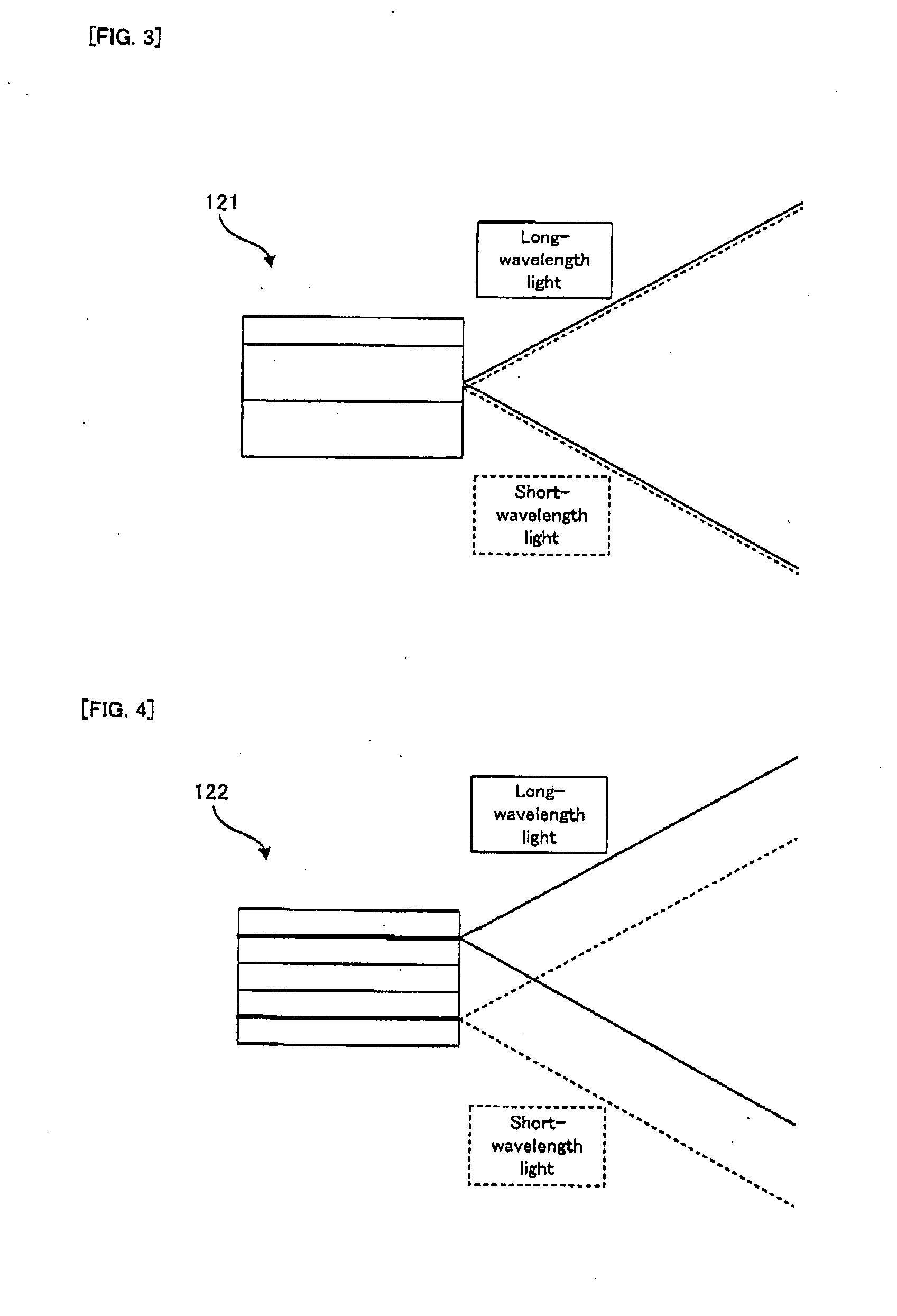
[0070]Firstly, the structure of a two-wavelength blood flow sensor apparatus in the present invention will be described with reference to FIG. 1 to FIG. 4. FIG. 1 is a plan view showing the structure of a sensor device in the two-wavelength blood flow sensor apparatus. FIG. 2 is an A-A′ cross sectional view in FIG. 1. FIG. 3 is a top view showing the structure of a hybrid two-wavelength laser by bonding. FIG. 4 is a top view showing the structure of a monolithic two-wavelength laser. Incidentally, in FIG. 1, for convenience of explanation, an illustration of a transparent substrate having a microlens is omitted.

[0071]As shown in FIG. 1 and FIG. 2, a sensor device 100 of the two-wavelength blood flow sensor apparatus in the first embodiment is provided with a sensor device substrate 110, a two-wavelength laser diode 120, reflecting mirrors 180, a transparent substrate 145 having a microlens 140, shielding films 147, a photo diode 150, electrodes 160, and wirings 170

[0072]On the senso...

second embodiment

[0096]As shown in FIG. 10, a two-wavelength blood flow sensor apparatus 200 in the second embodiment is provided with the photo diodes 150, each of which corresponds to respective one of the long-wavelength light and the short-wavelength light. Thus, each photo diode 150 is provided with the photo diode amplifier 230 and the A / D converter 240.

[0097]In the second embodiment, firstly, signals outputted from the laser diode drive circuit 210 allow the two-wavelength laser diode 120 to simultaneously emit the long-wavelength light and the short-wavelength light. Thus, the first switching circuit 220 (refer to FIG. 6) used in the first embodiment is not necessarily provided.

[0098]For the detection of the light reflected or scattered by the measured sample, for example, two photo diodes 150 having an optical band pass filter are used. The optical band pass filter includes a filter which transmits only the long-wavelength light and a filter which transmits only the short-wavelength light. ...


PUM

PropertyMeasurementUnit
wavelengthsaaaaaaaaaa
frequencyaaaaaaaaaa

Abstract

An emission sensor device includes a base (110), a light applying section (120) disposed on the base and adapted for applying light beams having different wavelengths to a subject in such a way that the light beams at least overlap with one another, and a light receiving section (150) disposed on the base and adapted for detecting light from the subject attributed to the applied light beams for each wavelength. The device has a small size and can collect predetermined types of information on the subject such as bioinformation with high accuracy.

Description

TECHNICAL FIELD[0001]The present invention relates to, for example, a light-emitting sensor apparatus which can measure a blood flow velocity and the like, and a method of inspecting biological information using the light-emitting sensor apparatus.BACKGROUND ART [0002]As this type of light-emitting sensor apparatus, there is an apparatus for applying light, such as a laser beam, to an object and for calculating a velocity or the like of the object from a change in wavelength caused by Doppler shift in reflection or scattering of the light. For example, there has been suggested a blood flow measuring apparatus which can measure a blood flow for blood vessels located in different depths by applying laser beams with different wavelengths from respective two laser diodes (refer to a patent document 1).Patent document 1: Japanese Patent Application Laid Open No. 2004-229920DISCLOSURE OF INVENTION Subject to be Solved by the Invention[0003]However, according to the technology as described...

Claims


Application Information

Patent Timeline
Patent Type & Authority Applications(United States)
IPC IPC(8): A61B5/1455A61B5/0265A61B5/026A61B5/0285G01N21/35
CPCA61B5/02028A61B5/0261A61B5/14546G01N21/359A61B2562/0242G01N2021/3144A61B5/14552
Inventor KIMURA, YOSHINORIONOE, ATSUSHISAWADA, RENSHI
Owner PIONEER CORP
Learn More