Hydraulically Actuated Expanding Spine Cage With Extendable Locking Anchor

a technology of expanding cage and locking anchor, which is applied in the field of expanding spine cage, can solve the problems of inability to expand and distract the endplate or fix the device, existing static cages do not reliably improve the space for neural elements, and the limitations of existing devices for interbody stabilization have important and significant limitations, so as to achieve high hydraulic pressure, effectively distract the intervertebral area, and minimize size and diameter

Active Publication Date: 2010-03-04
HOWMEDICA OSTEONICS CORP
View PDF98 Cites 156 Cited by
  • Summary
  • Abstract
  • Description
  • Claims
  • Application Information

AI Technical Summary

Benefits of technology

[0015]A minimally invasive downsized insertion tool, such as described in the above referenced applications, both inserts the unexpanded implant posteriorly and provides the hydraulic or mechanical lines communicating with the interior of the implant. The insertion tool may also provide a line for communicating the liquid or slurry bone graft material into the intervertebral space for subsequent fusion. Advantageously, hydraulic lines are small size tubing to allow for high hydraulic pressure without danger of the lines bursting.
[0016]Due to the mechan

Problems solved by technology

Existing devices for interbody stabilization have important and significant limitations, including inability to expand and distract the endplates or to fix the device in place to prevent relative movement between the device and an adjacent vertebral body.
Moreover, current interbody spacers do not maintain interbody lordosis and can contribute to the formation of a straight or even kyphotic segment and the clinical problem of “flatback syndrome.

Method used


Image

  • Hydraulically Actuated Expanding Spine Cage With Extendable Locking Anchor
  • Hydraulically Actuated Expanding Spine Cage With Extendable Locking Anchor
  • Hydraulically Actuated Expanding Spine Cage With Extendable Locking Anchor

Examples


Embodiment Construction

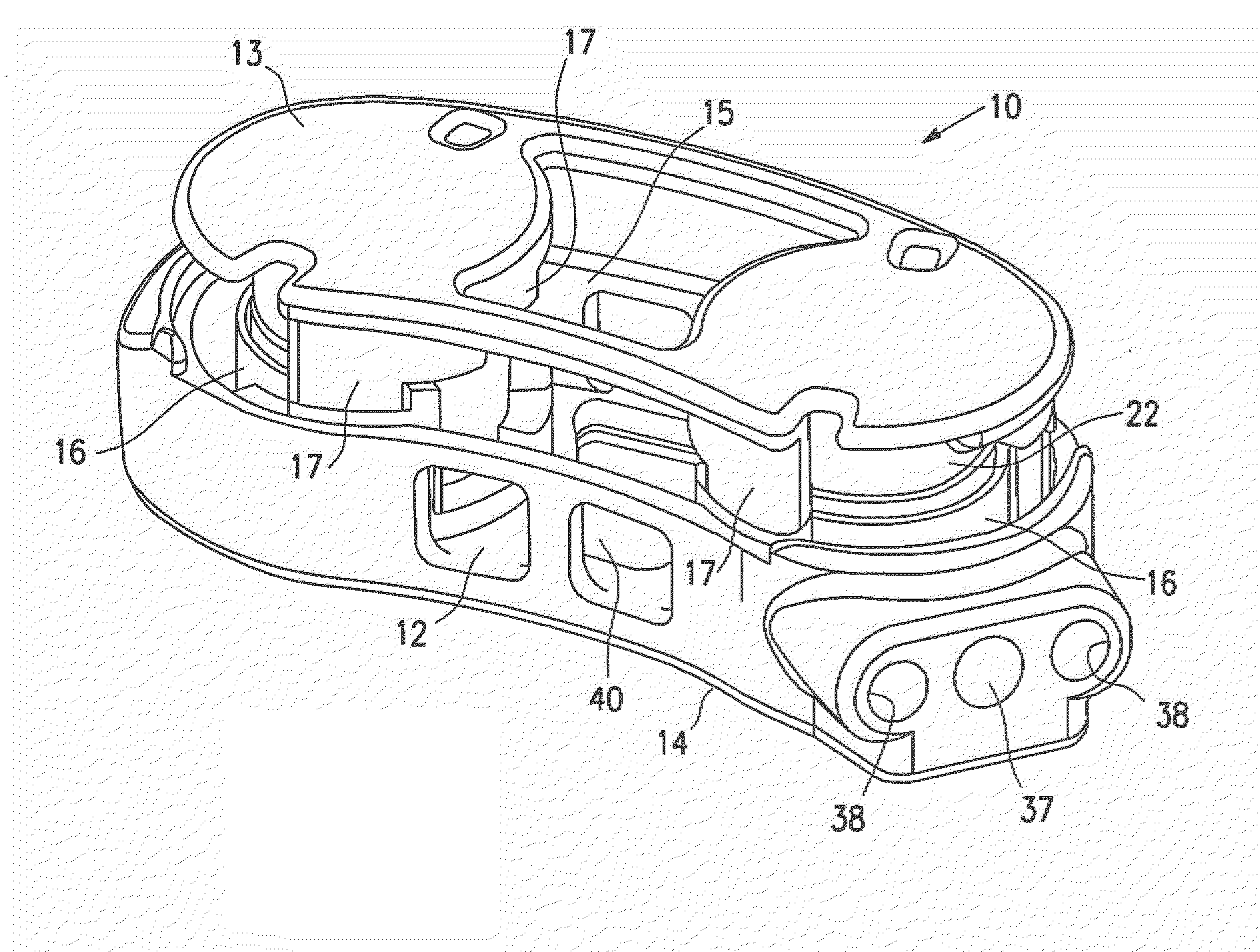
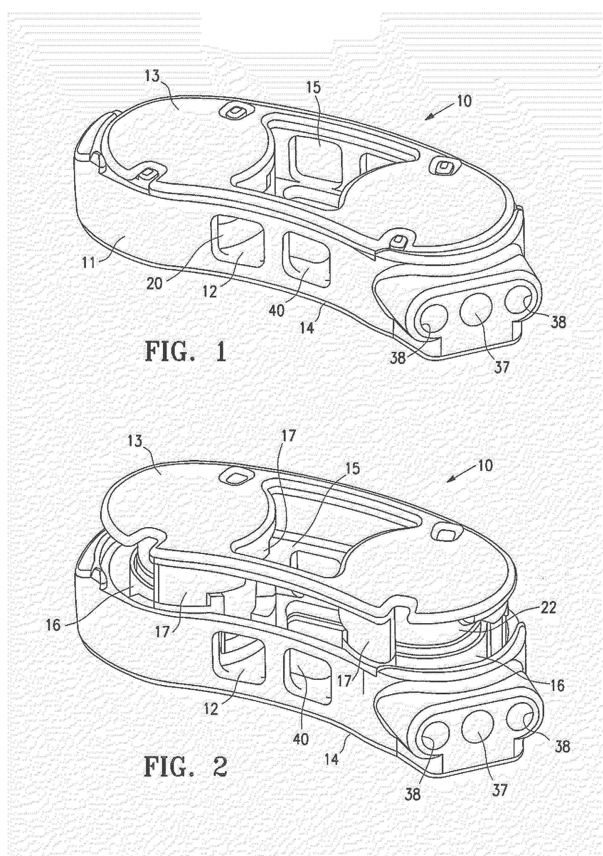
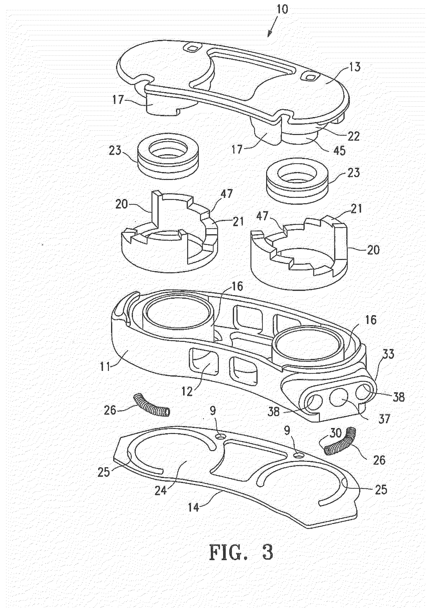
[0053]FIGS. 1-10B Illustrate an example of an intervertebral implant 10, a Selectively Expandable Cage (SEC), having features of the invention. The implant 10 generally includes a housing 11, a housing base 12, an interlocking top endplate 13, a bottom endplate 14, an interior cavity 15 within the housing 11 and a pair of cylinders 16. Upper lock supports 17 are attached to the underside of the top endplate 13 and have multi-stepped lower support surfaces 18 much like an inverted staircase. Lower lock supports 20, having multi-stepped upper support surfaces 21 surround cylinders 16 much like an upright staircase. Pistons 22 are secured to the under surface of top endplate 13. Seal members 23 are slidably disposed within the cylinders 16 and are mounted on pistons 22. The upper surface 24 of bottom end plate 14 is provided with locking actuator channels 25 which partially receive spring locking actuators 26. The base 12 of the housing 11 has arcuate slots 27 which are configured to s...


PUM


Abstract

A spinal implant which is configured to be deployed between adjacent vertebral bodies. The implant has at least one extendable support element with a retracted configuration to facilitate deployment of the implant and an extended configuration so as to expand the implant and effectively distract the disc space, stabilize the motion segments and eliminate pathologic spine motion. Angular deformities can also be corrected, and natural curvatures restored. Preferably, the implant has a minimal dimension in its unexpanded state that is smaller than the dimensions of the neuroforamen through which it typically passes to be deployed within the intervertebral space. The implant is provided with a locking system preferably having a plurality of locking elements to lock the implant in an extended configuration. Bone engaging anchors also may be provided to ensure secure positioning

Description

RELATED APPLICATION DATA[0001]This application is a continuation-in-part of U.S. Nonprovisional patent application Ser. No. 12 / 380,840, filed on Mar. 4, 2009, entitled “Lockable Spinal Implant,” which is a nonprovisional of U.S. Provisional Patent Application Ser. No. 61 / 201,518, filed on Dec. 10, 2008, entitled “Lockable Spinal Implant.” This application is also a continuation-in-part of U.S. Nonprovisional patent application Ser. No. 12 / 072,044, filed Feb. 22, 2008, entitled “Spinal Implant With Expandable Fixation.”[0002]This application is also related to U.S. patent application Ser. No. 11 / 692,800, filed Mar. 28, 2007, entitled “Selectively Expanding Spine Cage, Hydraulically Controllable in Three Dimensions for Vertebral Body Replacement,” which is a continuation-in-part of U.S. Nonprovisional patent application Ser. No. 11 / 535,432, filed Sep. 26, 2006, entitled “Selectively Expanding Spine Cage, Hydraulically Controllable in Three Dimensions for Enhanced Spinal Infusion,” whi...

Claims


Application Information

Patent Timeline
IPC IPC(8): A61F2/44
CPCA61F2/30742A61F2/44A61F2/4455A61F2002/30079A61F2002/3008A61F2002/30133A61F2002/30365A61F2002/30405A61F2002/30476A61F2002/30484A61F2002/30499A61F2002/30505A61F2002/30514A61F2002/30522A61F2002/30525A61F2002/3055A61F2002/30579A61F2002/30581A61F2002/30589A61F2002/30601A61F2002/30841A61F2002/482A61F2002/485A61F2210/009A61F2220/0025A61F2220/0033A61F2230/0015A61F2250/0007A61F2250/0069A61F2250/0098A61F2310/00017A61F2310/00023A61F2/442A61F2002/30495A61F2/484A61F2/482
Inventor KADABA, MURALISIMPSON, PHILIP J.ASHLEY, JOHN E.GILLESPIE, WALTER DEANGROTZ, THOMASMANSFIELD, III, GEORGE A.MATSUURA, DAVID G.PERETTI, RUDY
Owner HOWMEDICA OSTEONICS CORP
Why Eureka
Try Eureka