
Intervertebral fusion implant

a technology of intervertebral fusion and implant, which is applied in the field of fixation devices, can solve the problems of disc or vertebral body displacement, chronic back pain, and disc or vertebral body damage,

Active Publication Date: 2010-03-04
GLOBUS MEDICAL INC
View PDF94 Cites 271 Cited by
  • Summary
  • Abstract
  • Description
  • Claims
  • Application Information

AI Technical Summary

Benefits of technology

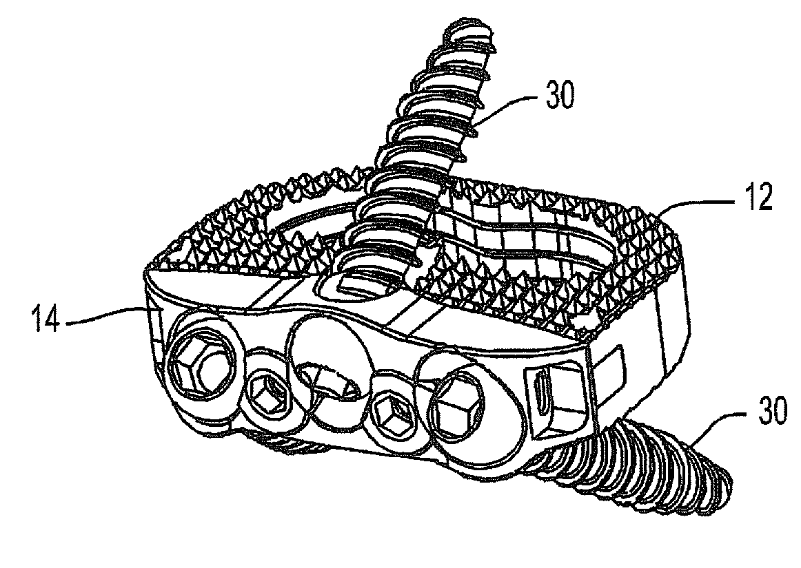
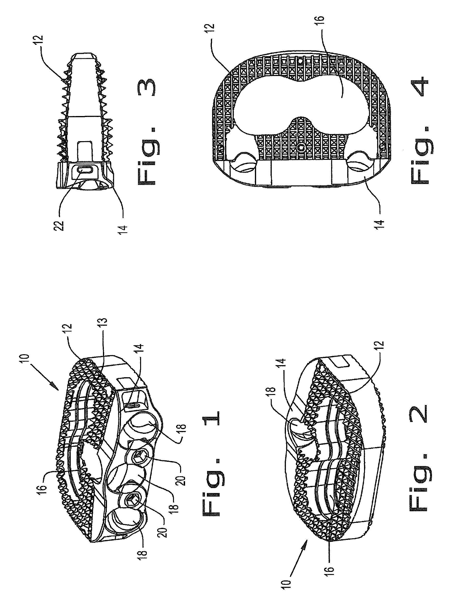
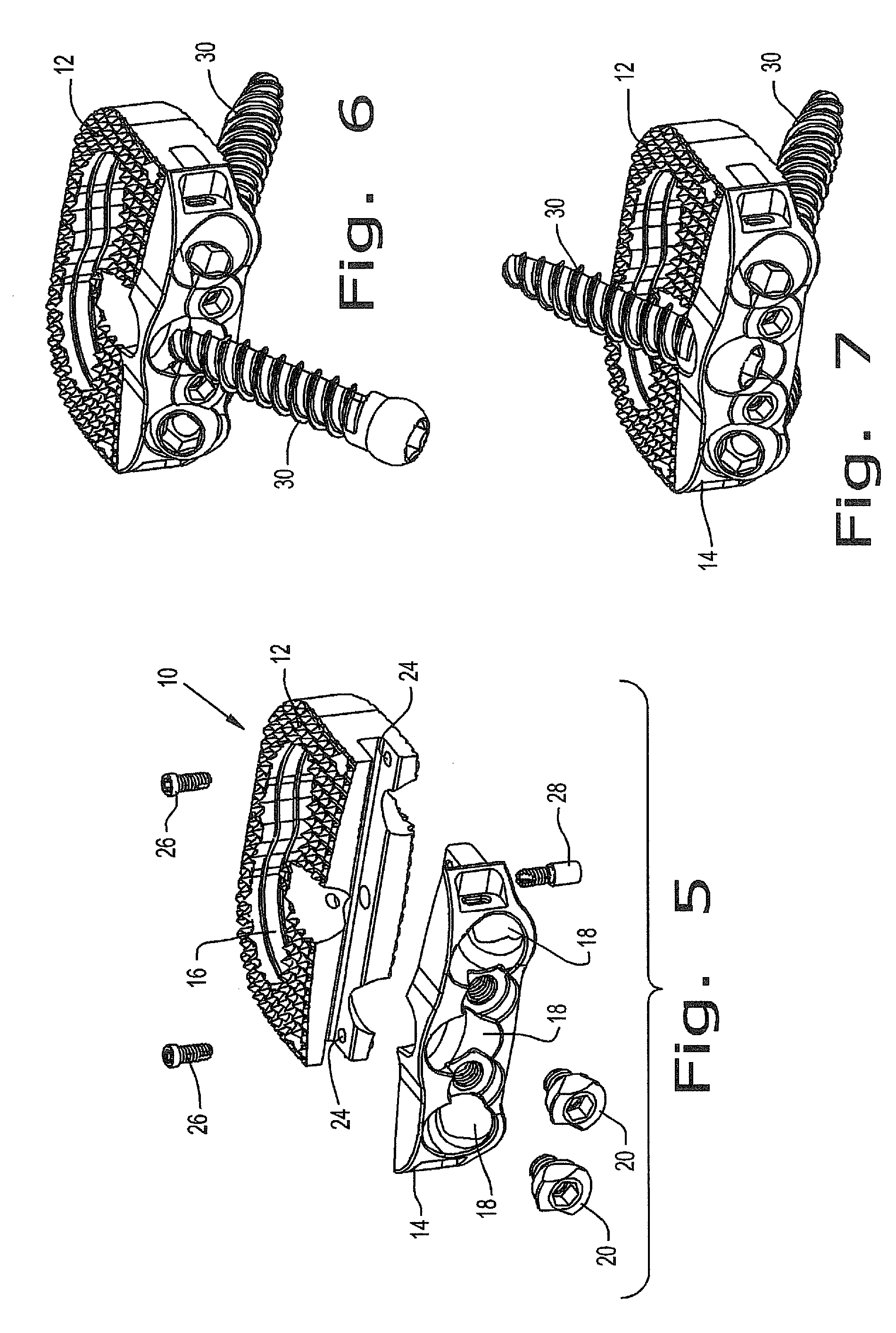
[0006]The present invention provides an intervertebral implant for implantation in a treated area of an intervertebral space between vertebral bodies of a spine. The implant includes a spacer portion having an inferior and superior surface, wherein the inferior and superior surfaces each have a contact area capable of engaging with anatomy in the treated area, and the inferior and superior surfaces define a through-hole extending through the spacer body. The present invention further provides screw holes extending from a side portion to the inferior and superior surfaces of the spacer portion and a plate portion rigidly coupled to the spacer portion through a coupling means, wherein the plate portion contains screws holes for receiving screws. A screw back out prevention mechanism is adapted on the plate portion and prevents the back out of screws from the screw holes.

Problems solved by technology

The spinal disc and / or vertebral bodies may be displaced or damaged due to trauma, disease, degenerative defects, or wear over an extended period of time.
One result of this displacement or damage to a spinal disc or vertebral body may be chronic back pain.
Plating systems independent of the spacers provide additional complications such as loosening and failure of the hardware.
Two common failures are the breakage of the plates, and the backing out of screws into soft tissues of the patient's body.
The backing out of the screws is typically a result of the screws failure to achieve a sufficient purchase in the bone, although the stripping of the screws has also been known to cause this problem.
Another common problems is that plating systems require “carpentry” work to match fit aspects of the vertebral bodies.

Method used


Image

  • Intervertebral fusion implant
  • Intervertebral fusion implant
  • Intervertebral fusion implant

Examples


Embodiment Construction

[0021]Embodiments of the disclosure are generally directed to flexible stabilization systems for use with the anterior, antero-lateral, lateral, and / or posterior portions of at least one motion segment unit of the spine. The systems of the invention are designed to be conformable to the spinal anatomy, so as to be generally less intrusive to surrounding tissue and vasculature than existing rigid stabilization systems.

[0022]Certain embodiments may be used on the cervical, thoracic, lumbar, and / or sacral segments of the spine. For example, the size and mass increase of the vertebrae in the spine from the cervical to the lumbar portions is directly related to an increased capacity for supporting larger loads. This increase in load bearing capacity, however, is paralleled by a decrease in flexibility and an increase in susceptibility to strain. When rigid immobilization systems are used in the lumbar segment, the flexibility is decreased even further beyond the natural motion restrictio...


PUM


Abstract

The present invention provides an intervertebral implant for implantation in a treated area of an intervertebral space between vertebral bodies of a spine. The implant includes a spacer portion having an inferior and superior surface, wherein the inferior and superior surfaces each have a contact area capable of engaging with anatomy in the treated area, and the inferior and superior surfaces define a through-hole extending through the spacer body. The present invention further provides screw holes extending from a side portion to the inferior and superior surfaces of the spacer portion and a plate portion rigidly coupled to the spacer portion through a coupling means, wherein the plate portion contains screws holes for receiving screws. A screw back out prevention mechanism adapted on the plate portion and prevents the back out of screws from the screw holes.

Description

FIELD OF THE INVENTION[0001]The present disclosure generally relates to a fixation device for positioning and immobilizing at least two adjacent vertebra. In particular, the present invention relates to a stand alone interbody fusion device for implementation in the spine.BACKGROUND OF THE INVENTION[0002]The vertebral spine is the axis of the skeleton on which all of the body parts “hang”. In humans, the normal spine has seven cervical, twelve thoracic and five lumbar segments. The lumbar spine sits upon the sacrum, which then attaches to the pelvis, and in turn is supported by the hip and leg bones. The bony vertebral bodies of the spine are separated by intervertebral discs, which act as joints but allow known degrees of flexion, extension, lateral bending, and axial rotation and translation.[0003]The typical vertebra has a thick anterior bone mass called the vertebral body, with a neural (vertebral) arch that arises from the posterior surface of the vertebral body. The central of...

Claims


Application Information

Patent Timeline
IPC IPC(8): A61F2/44A61B17/04A61B17/70
CPCA61F2/442A61F2/447A61F2/4684A61F2002/30004A61F2002/3008A61F2002/30383A61F2002/30436A61F2002/30492A61F2002/30517A61F2002/30604A61F2002/30787A61F2002/30794A61F2002/30843A61F2002/4475A61F2220/0025A61F2220/0041A61F2250/0014A61F2250/0098A61F2310/00023A61F2002/30433A61F2/4455A61B17/7059A61B17/8042A61F2/44A61F2/4465A61F2002/30001A61F2002/30593A61F2002/3079A61F2/30771A61F2002/30003A61F2002/30062A61F2002/30622A61F2002/30904A61F2220/0016
Inventor DUFFIELD, WILLIAM E.MCLAUGHLIN, COLMGRAY, JASONCALVERLEY, JAMIEADAMS, MARKRHODA, WILLIAM S.
Owner GLOBUS MEDICAL INC
Learn More