Exhaust gas cleaning system for diesel engine

a technology for cleaning systems and diesel engines, applied in the direction of machines/engines, exhaust treatment electric control, separation processes, etc., can solve the problems of clogging the dpf with excessive pm deposition, and achieve the effect of accurate measurement and high durability

Active Publication Date: 2010-03-11
NIHON KENKI CO LTD
View PDF3 Cites 27 Cited by
  • Summary
  • Abstract
  • Description
  • Claims
  • Application Information

AI Technical Summary

Benefits of technology

[0027]According to the present invention, a differential pressure across a filter can be measured accurately by u...

Problems solved by technology

However, when the load upon the diesel engine is light, since the temperature of the exhaust gases does not reach the high temperature level required for ...

Method used


Image

  • Exhaust gas cleaning system for diesel engine
  • Exhaust gas cleaning system for diesel engine
  • Exhaust gas cleaning system for diesel engine

Examples


Embodiment Construction

[0071]Hereunder, an embodiment of the present invention will be described referring to the accompanying drawings.

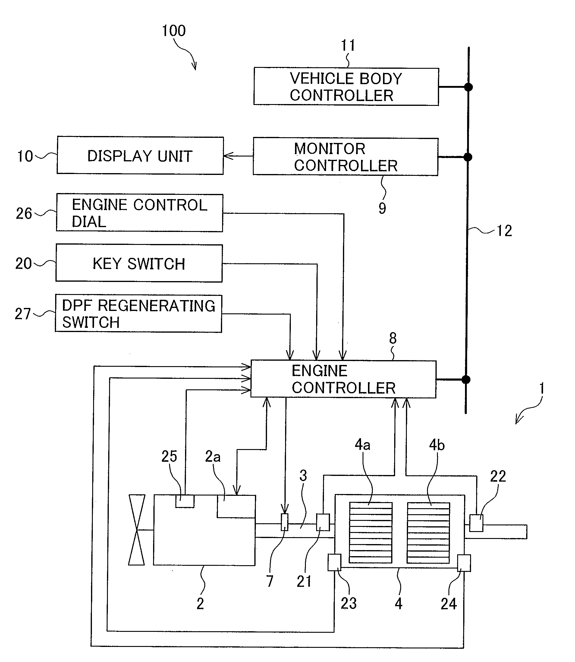
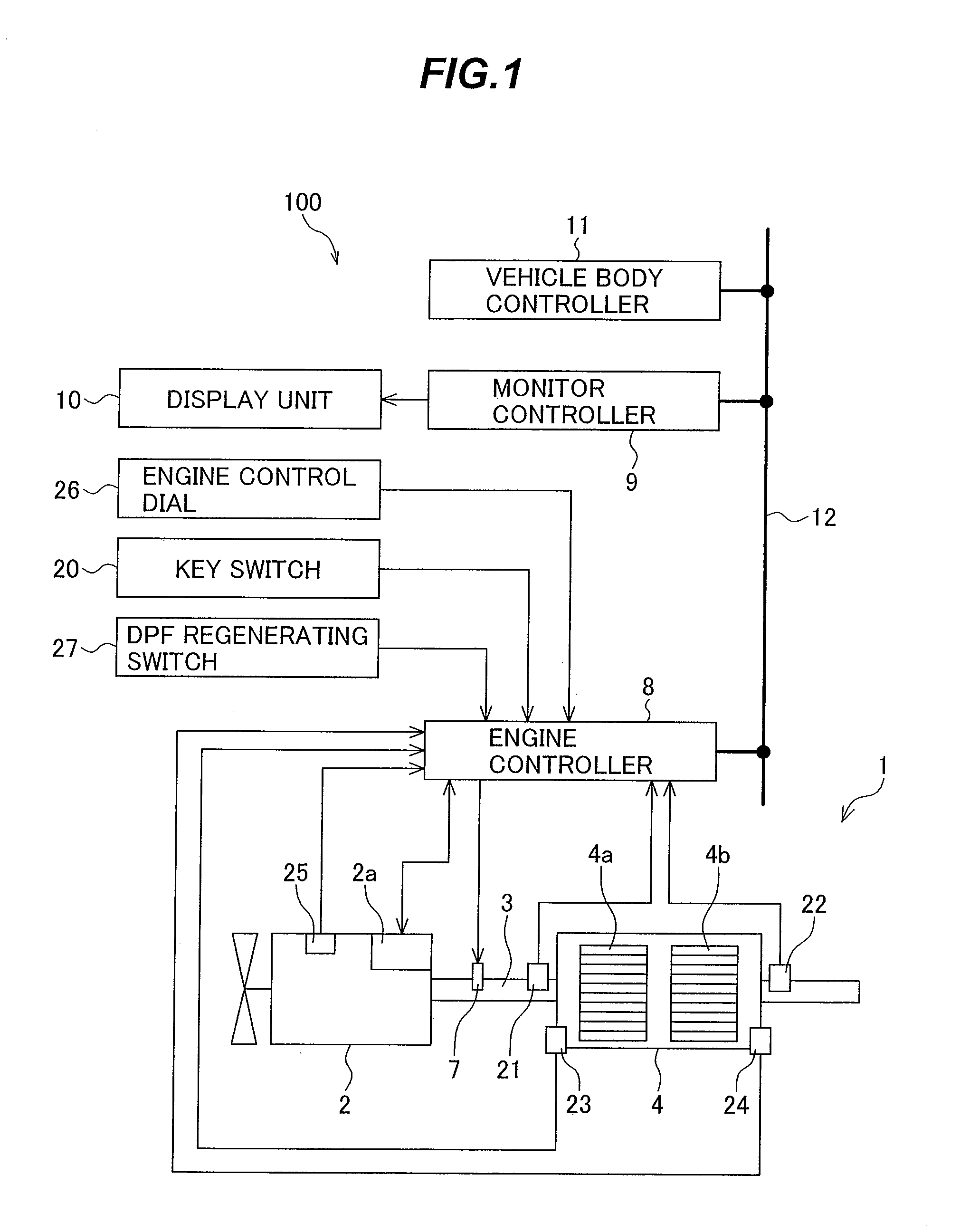
[0072]FIG. 1 is a diagram showing a system for cleaning exhaust gas emissions from an engineering vehicle according to an embodiment of the present invention, the diagram also showing an engine control system.

[0073]Referring to FIG. 1, reference numeral 2 denotes a diesel engine 2 (hereinafter, referred to simply as the engine), the engine 2 including an electronic governor 2a for controlling a speed of the engine 2, and an exhaust pipe 3 for releasing the exhaust gases from the engine 2 to the outside.

[0074]Reference numeral 100 denotes the engine control system, which includes a key switch 20 for assigning a starting instruction to the engine 2, an engine control dial 26 for specifying a target speed for the engine 2, an engine speed sensor 25 for detecting an actual speed of the engine 2, and an engine controller 8 for conducting required computing processes based upon...


PUM

PropertyMeasurementUnit
Timeaaaaaaaaaa
Pressureaaaaaaaaaa

Abstract

Each time a starting process for a diesel engine 2 is conducted and before the diesel engine 2 is started, any differences of the pressures P1 and P2 detected by first and second pressure sensors 21 and 22, respectively, with respect to a predetermined reference pressure value Pref, are computed and stored as first and second correction values ΔP1 and ΔP2, and then a differential pressure P12 across a particulate filter in the diesel engine 2 is computed using the pressure detection results of the first and second pressure sensors 21, 22 and the first and second correction values ΔP1,ΔP2. Thus, use of simply constructed and highly durable sensors during the detection of the differential pressure existing across the filter allows accurate measurement of this differential pressure.

Description

TECHNICAL FIELD[0001]The present invention relates generally to cleaning systems for exhaust gas emissions from diesel engines mounted in construction machines. More particularly, the invention concerns a diesel engine exhaust gas cleaning system adapted for computing a differential pressure across a filter and using this computed differential pressure to judge whether any particulate matter deposited in the filter is to be removed by burning-off to regenerate the filter.BACKGROUND ART[0002]Regulations on the exhaust gases emitted from internal combustion engines such as a diesel engine have been tightened each year. In response to the tightening of these regulations, exhaust gas filters and the technology relating to the catalysts used with the filters are also making rapid progress. For example, techniques for reducing the particulate matter (PM) included in diesel engine exhaust gases have already been developed, including the use of a diesel particulate filter (DPF).[0003]The DP...

Claims


Application Information

Patent Timeline
IPC IPC(8): F01N9/00F01N3/023
CPCF01N3/0253F01N3/035F01N3/106F01N9/002F01N2550/04F01N2560/06F01N13/0097F01N2560/14F01N2610/146F01N2900/0408F01N2900/14Y02T10/47F01N2560/08F01N2900/0416Y02T10/40B01D46/42F01N3/02F01N3/023F01N9/00
Inventor TSUKADA, HIDENOBUNAKAMURA, KAZUNORIKAMIYA, SHOHEI
Owner NIHON KENKI CO LTD
Why Eureka
Try Eureka