Electromagnetic differential speed control system for a fluid coupling device

a technology of differential speed control and fluid coupling, which is applied in the direction of fluid couplings, couplings, instruments, etc., can solve the problems of limiting the axial length of the tether for the front mount actuator for large fan applications, limiting the use of the rear mount actuator in narrow package applications, and still affecting the performance of the fan, etc., to achieve the effect of overcoming or minimizing the disadvantages of the disadvantag

Active Publication Date: 2010-03-11
BORGWARNER INC
View PDF7 Cites 13 Cited by
  • Summary
  • Abstract
  • Description
  • Claims
  • Application Information

AI Technical Summary

Benefits of technology

[0009]The present invention is an improvement over known

Problems solved by technology

The length of the tether for front mount actuators becomes a limiting factor for large fan applications.
The axial length of the tether for rear mount actuators limits such use in narrow package applications.
However, in some light duty gas engine applicat

Method used


Image

  • Electromagnetic differential speed control system for a fluid coupling device
  • Electromagnetic differential speed control system for a fluid coupling device
  • Electromagnetic differential speed control system for a fluid coupling device

Examples


Embodiment Construction

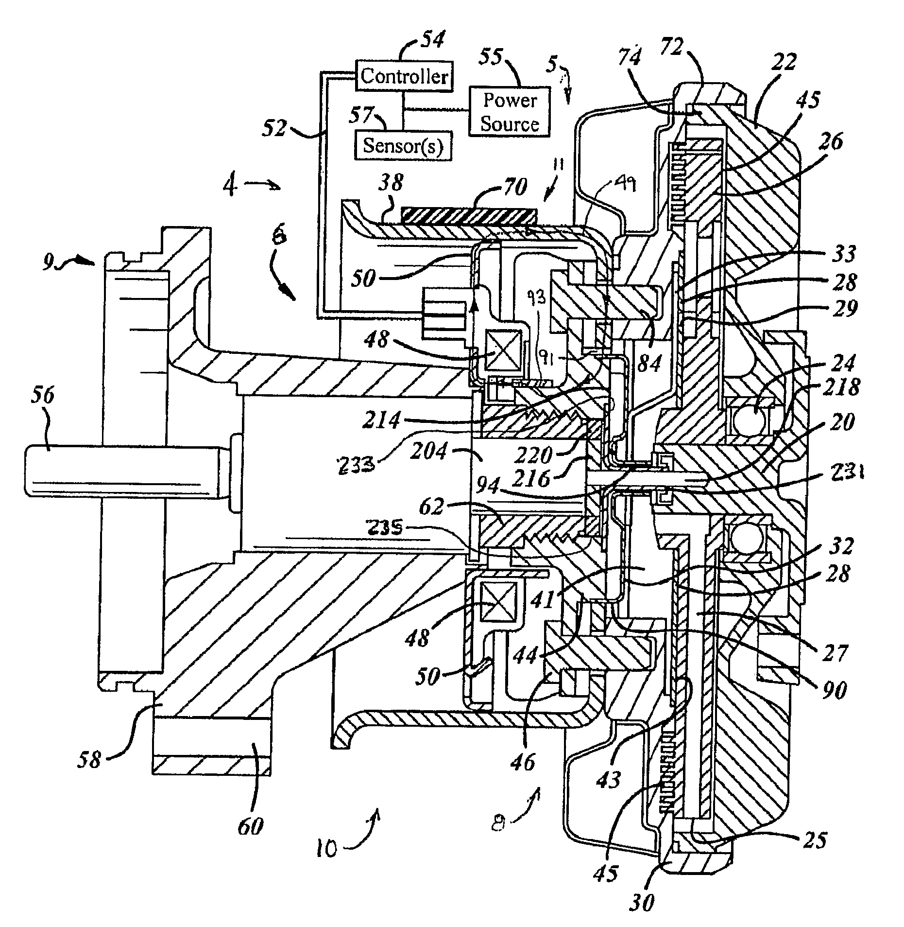
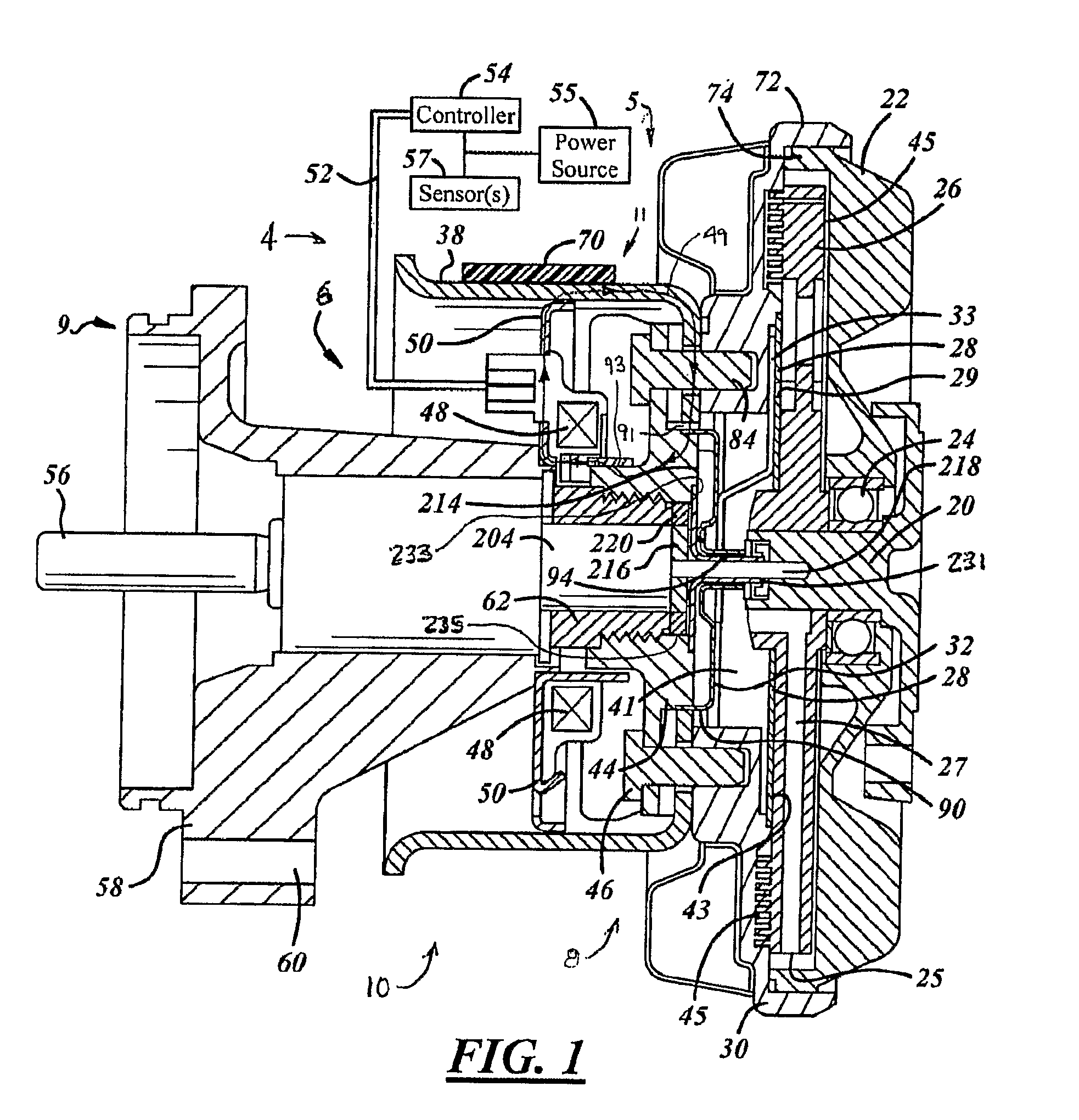
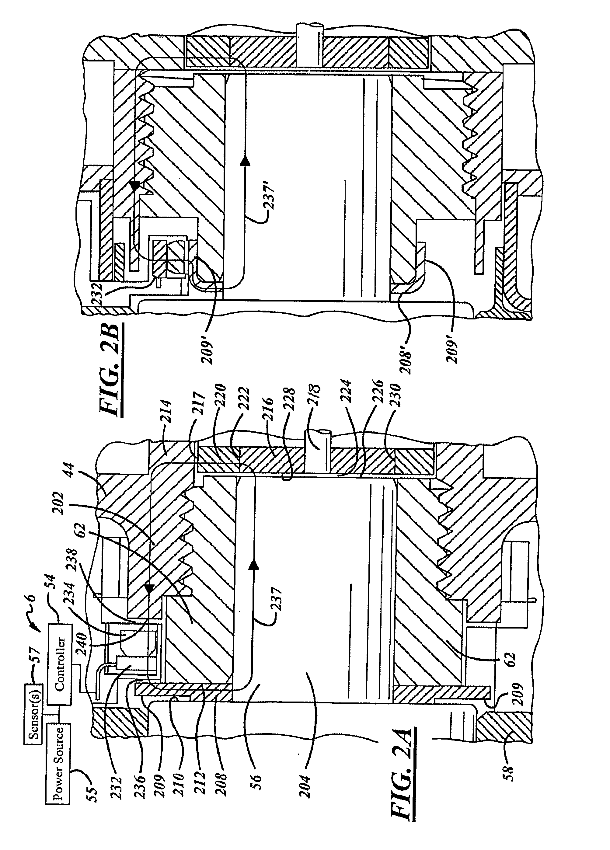
[0021]In the following Figures the same reference numerals will be used to refer to the same components. The present invention relates to and can be used with both viscous and non-viscous drive clutch devices. Although the present invention may be used advantageously in clutch devices having various configurations and applications, it is especially advantageous in an electronically controlled fluid-coupling device of the type used to drive a radiator cooling fan of an internal combustion engine. Although for simplicity the electronically controlled fluid-coupling device of the present invention will be described in connection with a cooling fan, it is to be understood that the invention is not limited to such uses and structures.

[0022]Also, a variety of other embodiments are contemplated having different combinations of the below described features of the present invention, having features other than those described herein, or even lacking one or more of those features. As such, it ...


PUM


Abstract

A speed monitoring system (6) for a fluid-coupling device (10) includes a hub (44) and a ring magnet (220). The hub (44) rotates at a first speed that is proportional to an input clutch speed of a fluidically engageable input member. The ring magnet (220) rotates at a second speed that is proportional to an output clutch speed of a fluidically engageable output member. A magnetic sensor (232) generates a differential speed signal of the ring magnet (220) relative to the first speed. A controller (54) generates an actual speed signal indicative of the second speed in response to said differential speed signal.

Description

TECHNICAL FIELD[0001]The present invention relates generally to clutch devices, fluid-coupling devices, and fan drive systems. More specifically, the present invention relates to a technique for electronically and accurately controlling the speed and operation of a fluid-coupling device.BACKGROUND OF THE INVENTION[0002]The present invention relates to clutch devices of the type including viscous type and non-viscous type.[0003]Although the present invention may be used advantageously in clutch devices having various configurations and applications, it is especially advantageous in a fluid-coupling device of the type used to drive a radiator cooling fan of an internal combustion engine, and will be described in connection therewith.[0004]Fluid-coupling devices (“fan drives”) of the viscous shear type have been popular for many years for driving engine cooling fans, primarily because their use results in substantial saving of engine horsepower. The typical fluid-coupling device operat...

Claims


Application Information

Patent Timeline
IPC IPC(8): F16D29/00G01P3/44
CPCF16D35/024F16D48/064F16D2500/10418F16D2500/5114F16D2500/30406F16D2500/5041F16D2500/10468F16D48/06F16D35/02F16D35/00
Inventor BOYER, RICK L.
Owner BORGWARNER INC
Why Eureka
Try Eureka