Bicycle suspension system employing highly predictable pedalling characteristics

a technology of bicycle suspension and pedalling characteristics, which is applied in the direction of friction roller based transmission, steering device, cycle equipment, etc., can solve the problems of high dcsl value, unpredictable response of rider, and highly predictable response, and achieve the effect of improving anti-squat characteristics

Active Publication Date: 2010-03-11
APROTECH
View PDF10 Cites 65 Cited by
  • Summary
  • Abstract
  • Description
  • Claims
  • Application Information

AI Technical Summary

Benefits of technology

[0005]The main frame and rear wheel triangle of the bicycle allow for the attachment of conventional bicycle components such as handlebars, a seat, the drivetrain and brakes in a standard configuration. The rear wheel triangle also has attachment points to linkage members in specific locations that contribute to controlling the motion of the rear wheel axle.
[0006]The first and the second link contribute to controlling the motion of the rear wheel axle and thus the rate of chainstay lengthening. Both links rotate clockwise when viewed from the drivetrain side of the bike. In addition to contributing to controlling the rear axle motion, the second link, in some but not all configurations, also allows for the attachment of the shock absorber, and its configuration controls the ratio of the shock absorber compression relative to the rear wheel compression.
[0007]The configuration of the linkage of the rear wheel suspension system controls the motion of the intersection of the force lines running from pivot to pivot along the first and second linkage members. This intersection is commonly referred to as the instant center of the linkage. As the system is compressed, the instant center moves in a generally rearward and downward trajectory, but always in front of the most forward pivot of the first linkage member. This motion of the linkage instant center is responsible for the improved anti-squat characteristics.

Problems solved by technology

However, it is undesirable to have high values for the dCSL at points farther in the suspension's compression as this creates a pull on the pedals when a larger bump is encountered as when riding over very rough terrain.
The known systems that employ a reduction in dCSL as the system is further compressed generally display a curved relationship between dCSL and the vertical wheel travel resulting in unpredictable response to the rider when encountering bumps of various sizes.
This results in highly predictable response.

Method used


Image

  • Bicycle suspension system employing highly predictable pedalling characteristics
  • Bicycle suspension system employing highly predictable pedalling characteristics
  • Bicycle suspension system employing highly predictable pedalling characteristics

Examples


Embodiment Construction

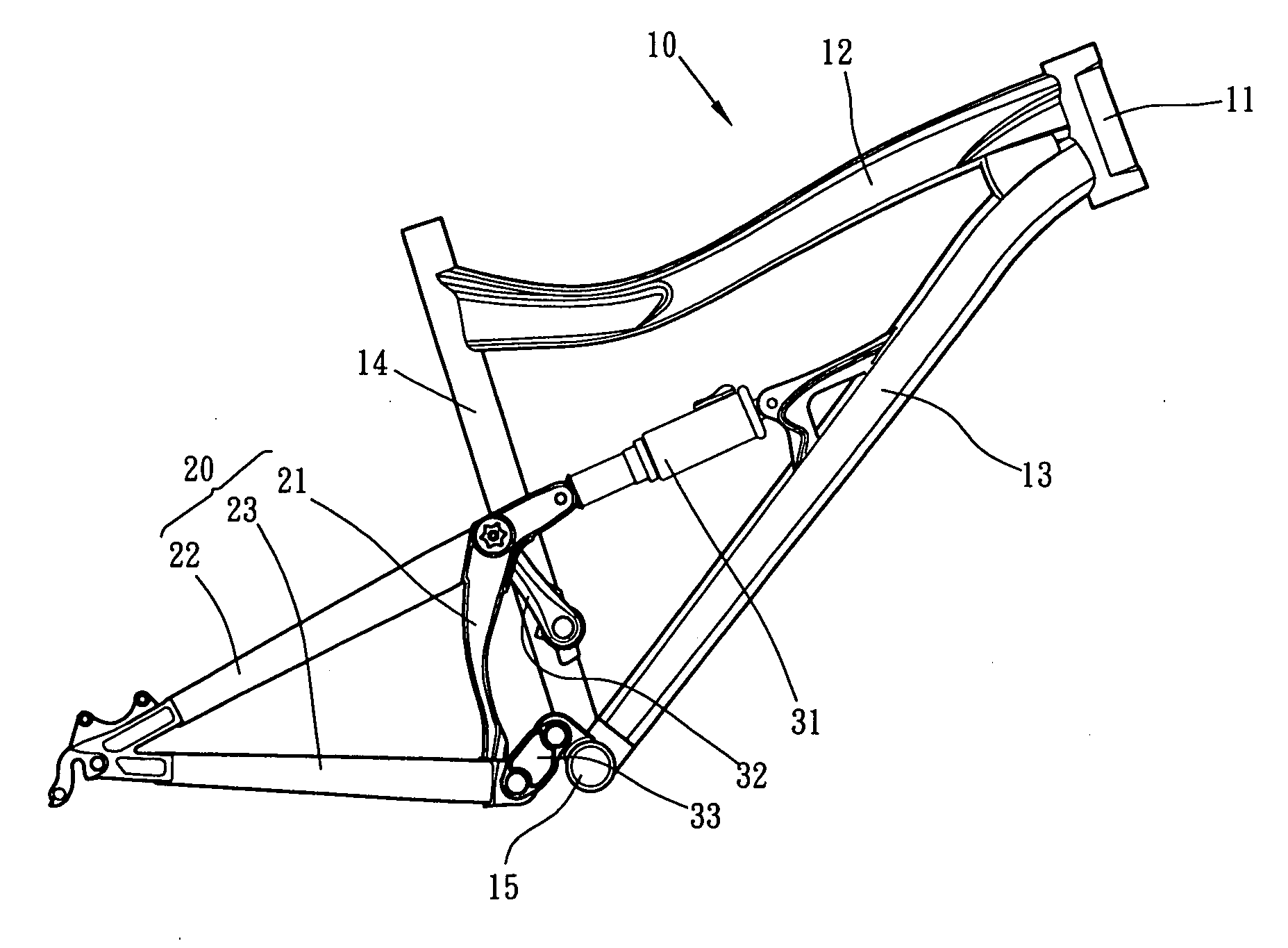
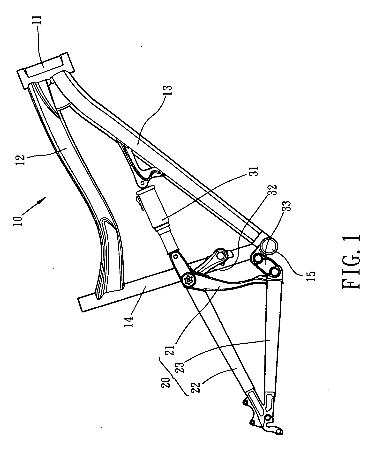
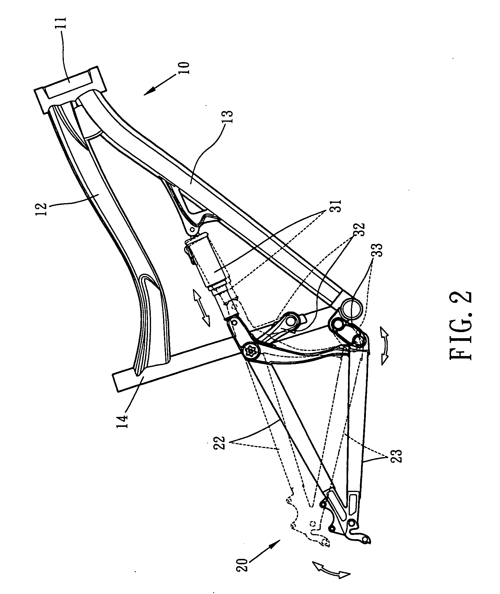
[0016]FIG. 1 and FIG. 2 depicts a preferred embodiment of a rear wheel suspension system of a bicycle of the present invention. The bicycle main frame 10 generally includes a seat tube 14 and a down tube 13 both of which are attached to a bottom bracket 15 that houses a pedal assembly, a top tube 12, together with the down tube 13 attached to the head tube 11, and a front fork (not shown). There is a first location above the bottom bracket pivot axis and proximate the bicycle chain drive force line for the pivotal connection to the first linkage member 33 of the rear wheel suspension system, and a second location above the first location for the pivotal connection to the second linkage member 32. Additionally, there is a connection on the down tube 13 for the forward connection of the shock absorber 31. These elements are typically welded or otherwise secured together to define the main frame 10 of the bicycle. Although the main frame 10 typically includes all of the foregoing membe...


PUM


Abstract

A bicycle rear suspension system that includes a main frame and a rear wheel suspension system, the main frame generally is comprised of a seat tube, a down tube, a top tube, and a head tube. The rear wheel suspension system consists of a first linkage member, a rear wheel swingarm, and a second linkage member. The rear wheel suspension system allows for a preferential linear decrease in rate of chainstay lengthening combined with a preferential linear decrease in rate of acceleration anti-squat with the value of 100% anti-squat occurring at the statically weighted sag point.

Description

FIELD OF THE INVENTION[0001]The present invention relates to a bicycle rear suspension system which offers improved pedaling and bump absorption performance by means of combined controlled linear chain stay lengthening and anti-squat characteristics through the use of a linkage system.BACKGROUND OF THE INVENTION[0002]There are numerous bicycle suspension systems in use today to improve performance. Many of these systems tune two important parameters that relate to unwanted suspension motion when the system is responding to pedal inputs. Other systems attempt to optimize the braking response of the suspension system. The present invention tunes both of the pedal performance parameters together to behave in a linear relationship so that their combined effect is highly predictable to the rider. Additionally, a third parameter that is related to improved braking performance is also tuned in the present invention. This parameter is the braking anti-squat percentage. This parameter is als...

Claims


Application Information

Patent Timeline
Patent Type & Authority Applications(United States)
IPC IPC(8): B62K25/28B62K25/04B62K3/02B62K19/00
CPCB62K25/286B62K25/26
Inventor EARLE, DAVID
Owner APROTECH
Why Eureka
Try Eureka