Loose flange pipe joint

a loose flange and pipe joint technology, applied in fluid pressure sealed joints, cable terminations, mechanical devices, etc., can solve the problems of water leakage, operation delay and pipe damage, and difficulty in matching the bolt holes of both flanges with each other, so as to prevent the width and outside diameter of the loose flange is easy to be transformed by compression, and the effect of preventing off slipping down or falling

Inactive Publication Date: 2010-03-11
NOWLA ENG
View PDF23 Cites 34 Cited by
  • Summary
  • Abstract
  • Description
  • Claims
  • Application Information

AI Technical Summary

Benefits of technology

[0037]The loose-flange type fitting according to the present invention is closely sealed with an elastic gasket that is relatively easy to be transformed by compression. It is therefore locked up by means of the bolts to such an extent that the connection between both the pipes endures a tubeside pressure. It is not necessary to lock up the gasket such strictly as a sheet packing. The loose-flange type fitting of the present invention has an annular reinforcing ring and the elastic gasket arranged between both collars of connection pipes, in which both sides and outer circumferential face of the elastic gasket are pressed against the pipe collars and a reinforcing ring so that the seal contact therebetween can increase in degree together with rising of a tubeside internal pressure.
[0038]The loose-flange type fitting of the present invention does not need to be locked excessively with bolts and nuts owing to this high sealing, which does not cause problems for the occurrence of a water leak when locking and in use. In the loose-flange type fitting, the number of the locking bolt may be reduced nearly in one half from a conventional fitting and the width and the outside diameter of the loose flange may be smaller relatively because hard locking with bolts and nuts is not necessary. It is easy to secure a workspace within the operation place, consequently pipe connecting works becomes easy.
[0039]The loose-flange type fitting does not cause the occurrence of a water leak under every condition because the gasket is not deformed inward and thus a sealing between both the pipes does not decrease in degree by arranging the supporting ring inside the elastic gasket even though the tubeside pressure becomes negative.
[0040]While both the loose flanges are connected to each other with several bolts and nuts, the reinforcing ring is disposed between the end faces of the pipe collars and then each bolt is passed through the open hole of the ring extension to lock both the flanges, therefore the reinforcing ring and the elastic gasket is prevented from off slipping down or falling. As the inside diameter of the elastic gasket is the same or larger than that of the connection pipes, circulating fluid can pass smoothly through the inside of the fitting.

Problems solved by technology

In a stationary flange type fitting, the flange is welded on the edge of the pipe, therefore it is not easy to match bolt holes of both the flanges with each other during piping works.
The bolt holes must be matched even if each one of the metallic pipes is twisted forcibly, which tends to cause an operation delay and pipe damage.
It is feared that the packing 108 cracks under a hard tightening of these bolts and nuts and thus a water leak is generated.
It is hard to secure a workspace within the operation place owing to heavy weight and large outside diameter of the flange.

Method used


Image

  • Loose flange pipe joint
  • Loose flange pipe joint
  • Loose flange pipe joint

Examples


Embodiment Construction

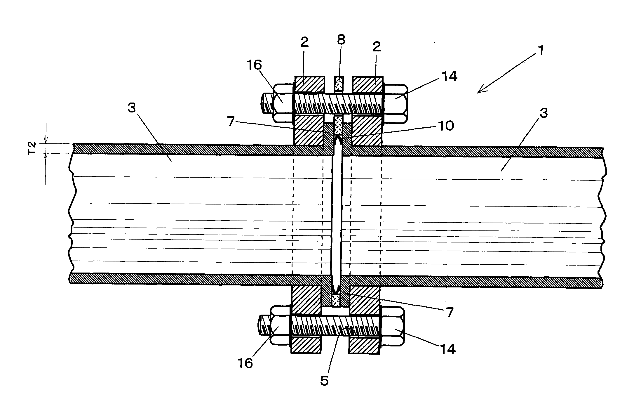
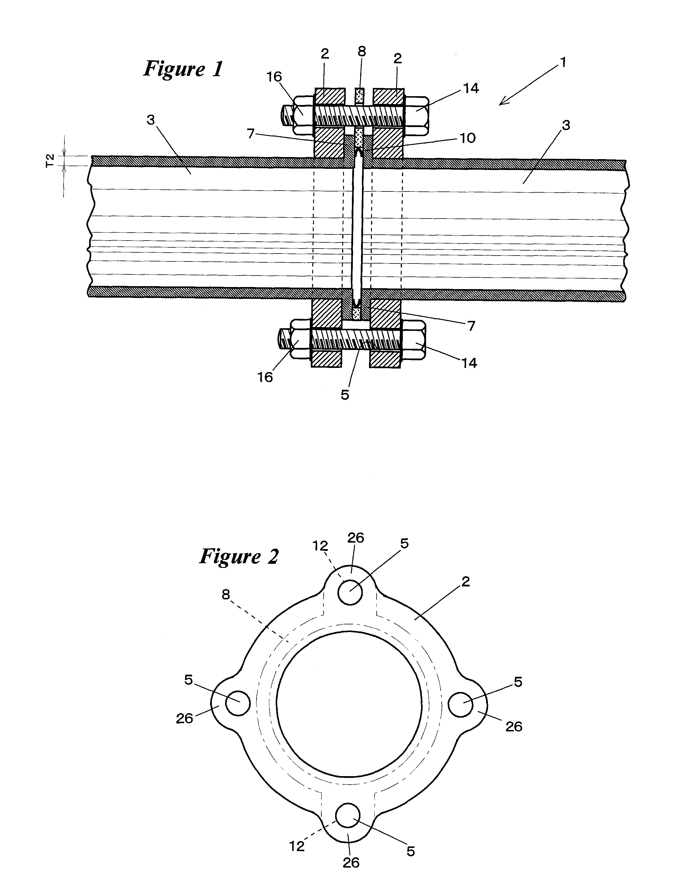
[0065]The present invention is now illustrated on the basis of examples, but the present invention will not be limited to the examples. In a loose-flange type fitting 1 illustrated in FIG. 1, metallic loose flanges 2 and 2 have substantially a doughnut-shaped plane as shown in FIG. 2, which is in existence separately from pipes 3 and 3 to be connected. The pipes 3 and 3 are a metallic conduit with like or corresponding diameter. On the flange 2, four bolt holes 5 are formed at regular intervals in the circumferential direction, whose inside diameter is substantially equal to the outside diameter of the pipe 3. The diameter of a virtual circle passing through the radial outside of the inner circumferential faces of each hole 5 is larger than the outside diameter of a collar 7 of the pipe 3 or a reinforcing ring 8.

[0066]Each circular flange 2 is fitted onto the pipes 3 before flanging the pipe end. Instead of the circular flange 2, a loose flange of two half segments (not shown) may b...


PUM

PropertyMeasurementUnit
angleaaaaaaaaaa
included angleaaaaaaaaaa
axial widthaaaaaaaaaa

Abstract

The loose-flange type fitting according to the present invention is closely sealed with an elastic gasket whose both the sides and outer circumferential face are pressed against a pipe collars and a reinforcing ring so that the seal contact therebetween increases in degree together with rising of a tubeside internal pressure, in which the seal material comprising an annular elastic gasket, a metallic reinforcing ring disposed on the outer circumferential side of the elastic gasket and the inner circumferential face of the elastic gasket having substantially a V-shaped cross-section and the axial width of the gasket being broader than that of the reinforcing ring under non-compression conditions.

Description

TECHNICAL FIELD[0001]The present invention relates to a loose-flange type fitting in which both the sides and outer circumferential face of an elastic gasket are pressed against a pipe collars and a reinforcing ring so that the seal contact therebetween increases in degree together with rising of a tubeside internal pressure.BACKGROUND ART[0002]In a plumbing such as water-supply or air-conditioning works, a piping diagram is designed prior to a piping operation, and subsequently metallic pipes are previously connected and / or bent in a factory on the base of this piping diagram. So as to connect linearly metallic pipes to each other, a flanged type fitting is preferable in terms of the mechanical strength of connecting section, a piping operation for a large-diameter pipe or the like. In a stationary flange type fitting, the flange is welded on the edge of the pipe, therefore it is not easy to match bolt holes of both the flanges with each other during piping works. The bolt holes mu...

Claims


Application Information

Patent Timeline
Patent Type & Authority Applications(United States)
IPC IPC(8): F16L23/024F16L17/06
CPCF16L17/073F16L23/18F16L23/0283F16L23/024F16L23/026F16L23/028F16L23/16
Inventor MATSUMOTO, SHIGEYUKIHOTTA, SUSUMU
Owner NOWLA ENG
Why Eureka
Try Eureka