Voltage/current conversion circuit

a voltage/current conversion and circuit technology, applied in pulse technique, instruments, computing operations for integration/differentiation, etc., can solve the problems of increasing power consumption, difficult to reduce the power consumption of the voltage/current conversion circuit, and more difficult to carry out the above-mentioned operation, etc., to achieve low power consumption, high power consumption, and high accuracy

Inactive Publication Date: 2010-03-11
RENESAS ELECTRONICS CORP
View PDF3 Cites 2 Cited by
  • Summary
  • Abstract
  • Description
  • Claims
  • Application Information

AI Technical Summary

Benefits of technology

[0020]In the voltage / current conversion circuit according to an exemplary embodiment of the present invention, in the first state, the sampling of the input signal voltage is carried out with high accuracy using the first and second capacitors serving as passive elements, and the voltage / current conversion is performed to follow the input signal by using the first and second resistors for determining a voltage / current conversion ratio. In the second state, the differential output current is determined based on a sampling voltage of each of the first and second capacitors at the time of switching from the first state, and each of the third and fourth resistors for determining the voltage / current conversion ratio. Though the differential amplifier has a predetermined operation delay, the voltage / current conversion circuit is capable of correcting the delay even in the second state. Further, the correction can be achieved at high speed, because the output difference of the differential amplifier caused due to the correction is small. Therefore, the voltage / current conversion circuit requires no high-speed amplifier for amplifying a high-speed input signal which requires high power consumption.
[0021]A voltage / current conversion circuit according to an exemplary embodiment of the present invention is capable of using an amplifier having low power consumption even when the input signal has a high-frequency, and of suppressing an increase in power consumption.

Problems solved by technology

When the input signal has a high frequency, however, it is difficult for the amplifier G11 to perform an operation for the voltage / current conversion to follow the input signal voltage with accuracy during the sampling period S1 shown in FIG. 6, and to charge the sampling capacitor.
Moreover, when the sampling frequency increases, the sampling period is shortened, which makes it more difficult to carry out the above-mentioned operation.
In the amplifier for amplifying the high-frequency signal, however, a bias current inevitably increases, resulting in an increase in power consumption.
This makes it difficult to reduce the power consumption of the voltage / current conversion circuit.

Method used


Image

  • Voltage/current conversion circuit
  • Voltage/current conversion circuit
  • Voltage/current conversion circuit

Examples


first exemplary embodiment

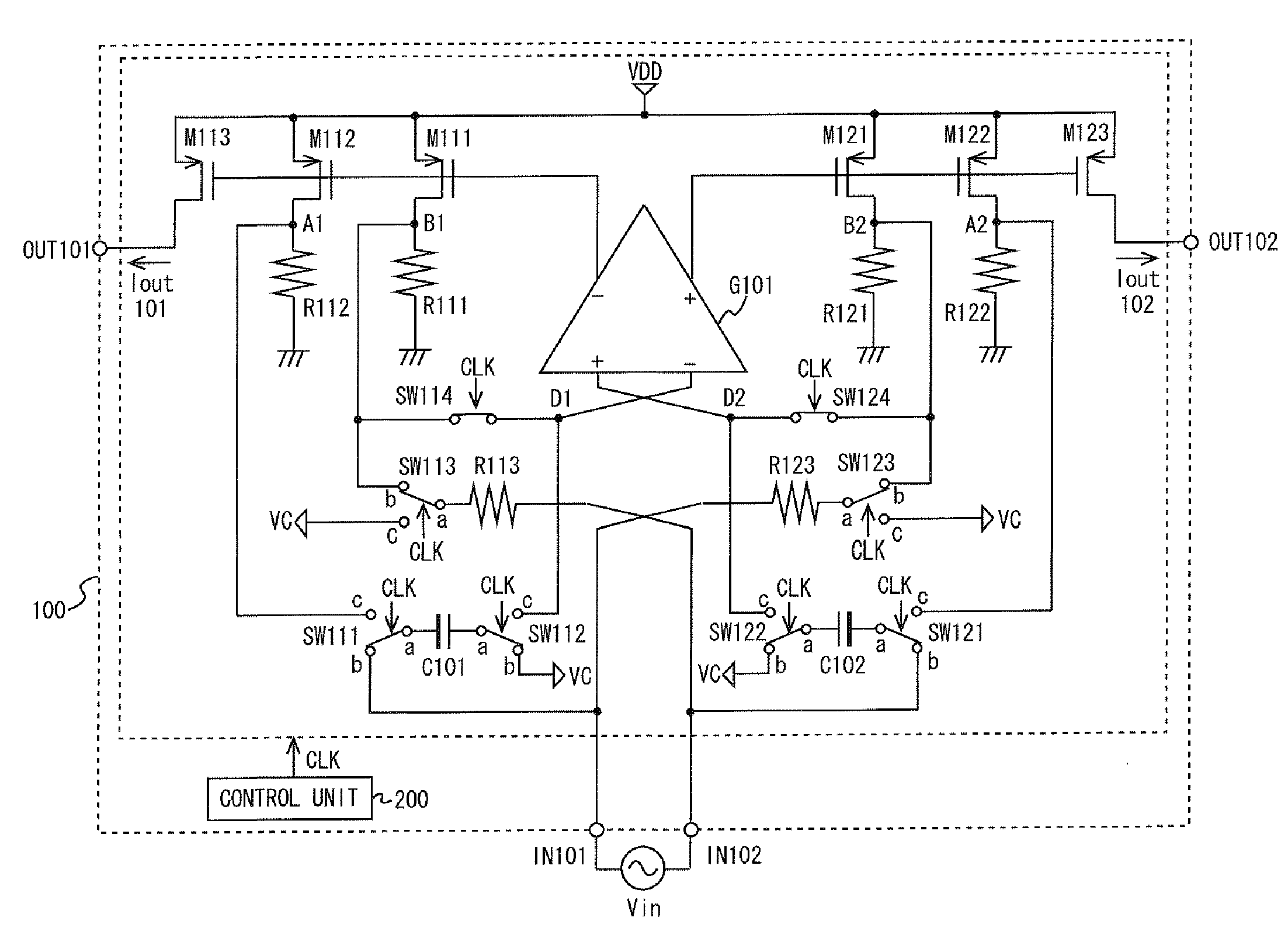
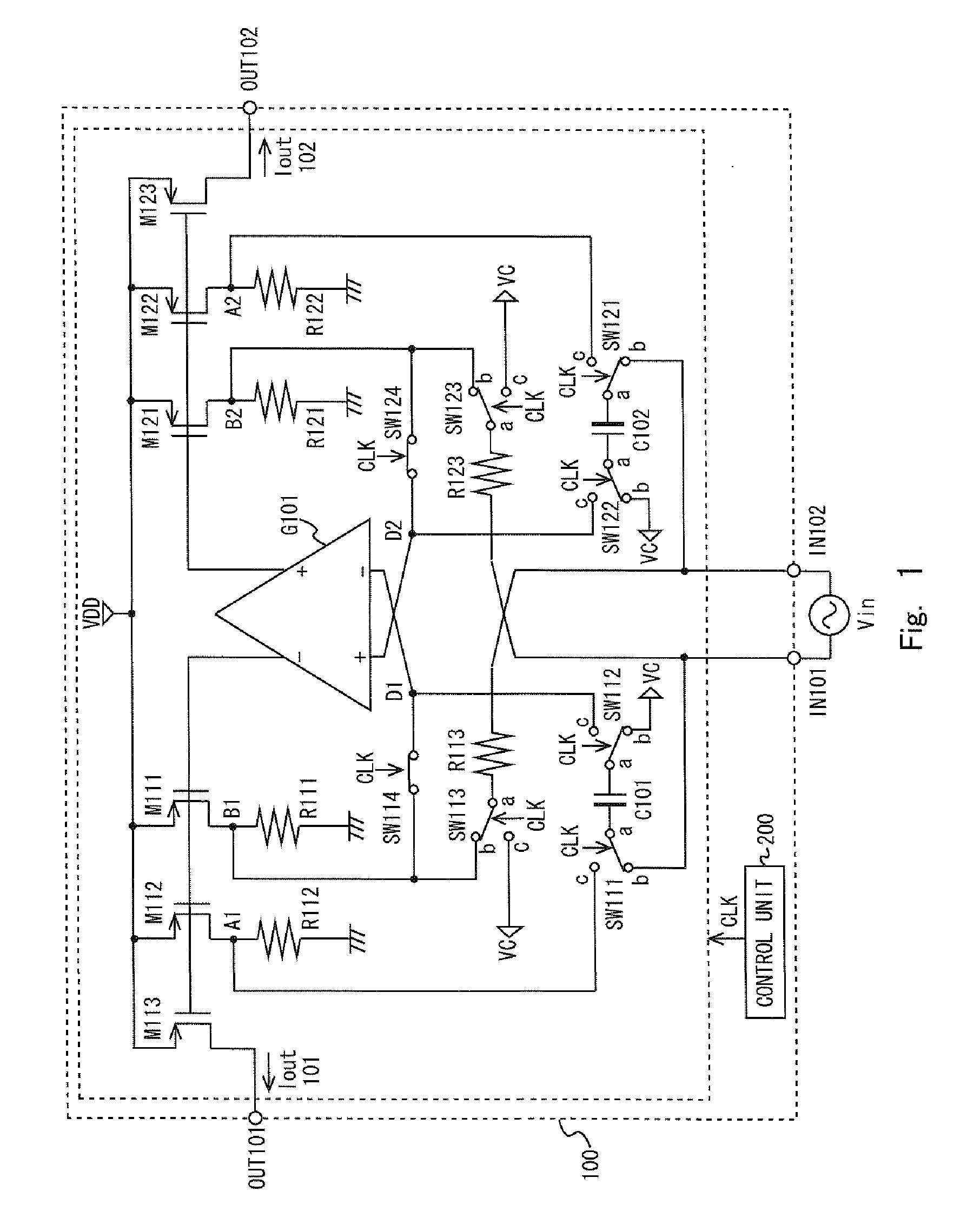
[0030]FIG. 1 shows a configuration example of the voltage / current conversion circuit 100 according to this exemplary embodiment. As shown in FIG. 1, the voltage / current conversion circuit 100 includes an amplifier G101, capacitors C101 and C102, PMOS transistors M111 to M113 and M121 to M123, resistors R111 to R113 and R121 to R123, switches SW111 to SW114 and SW121 to SW124, a control unit 200, input terminals IN101 and IN102, and output terminals OUT101 and OUT102.

[0031]The input terminals IN101 (first input terminal) and IN102 (second input terminal) are each connected to an external signal source for outputting a high-frequency signal (e.g., 10 MHz). Thus, each of the input terminals IN101 and IN102 receives an input signal voltage Vin output from the external signal source.

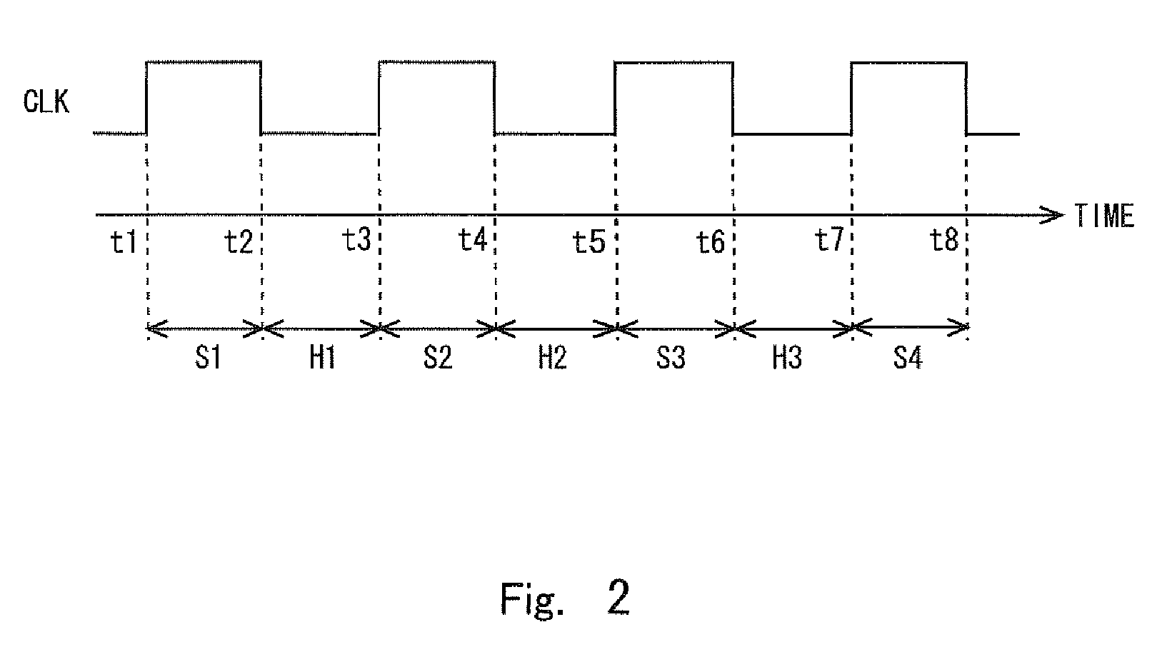
[0032]The control unit 200 outputs a clock signal CLK to each of the switches SW111 to SW114 and SW121 to SW124. In response to the clock signal CLK, the voltage / current conversion circuit 100 switches betwee...


PUM


Abstract

Provided is voltage/current conversion circuit including: first and second capacitors; first and second resistors each connected to input terminal; first and second current sources; third and fourth resistors connected to current sources; differential amplifier for controlling the current sources; control unit for performing control, in first state, the input terminal is connected to the first and second capacitors; one input of the differential amplifier is connected to the first resistor and output of the first current source; the other input of the differential amplifier is connected to the second resistor and output of the second current source, and in second state, the second capacitor is connected between the output of the first current source and the one input of the differential amplifier, the first capacitor is connected between the output of the second current source and the other input of the differential amplifier.

Description

BACKGROUND[0001]1. Field of the Invention[0002]The present invention relates to a voltage / current conversion circuit.[0003]2. Description of Related Art[0004]Reference is now made to FIG. 5 which illustrates the configuration of a sampling-type voltage / current conversion circuit 1 disclosed in “A 35MS / s and 2V / 2.5V Current-mode Sample-and-Hold Circuit with an Input Current Linearization Technique”, Asian solid-state circuits conference, 2005 (IEEE), Paper No. P2-20, pp. 445 to 448, as an example of conventional voltage / current conversion circuits. As shown in FIG. 5, the voltage / current conversion circuit 1 includes resistors R11 and R21, current sampling circuits 11 and 21, current mirror circuits 12 and 22, and a sampling error correction circuit 30. Input terminals IN1 and IN2 of the voltage / current conversion circuit 1 are each connected to an input signal source to receive an input signal Vin. It is assumed herein that a voltage input to the input terminal IN1 is denoted by Vin...

Claims


Application Information

Patent Timeline
Patent Type & Authority Applications(United States)
IPC IPC(8): H02M11/00
CPCG11C27/026H03F3/45475H03F2203/45136H03F2203/45511H03F2203/45512H03F2203/45528H03F2203/45618H03F2203/45536H03F2203/45562H03F2203/45594H03F2203/45614H03F2203/45616H03F2203/45534
Inventor ETOU, TOSHIYUKI
Owner RENESAS ELECTRONICS CORP
Why Eureka
Try Eureka