
Power series predistorter and control method thereof

a technology of power series and predistorters, applied in the direction of digital transmission, amplifier modifications to reduce non-linear distortion, baseband system details, etc., can solve the problem that the conventional control method provided to follow temporal changes or temperature changes may not be able to follow the dynamic changes in transmission output power, increase offset values may increase the setting error of vector adjusters, etc. problem, to achieve the effect of minimizing distortion components, minimizing calculation costs, and minimizing distortion components

Inactive Publication Date: 2010-03-11
NTT DOCOMO INC
View PDF3 Cites 11 Cited by
  • Summary
  • Abstract
  • Description
  • Claims
  • Application Information

AI Technical Summary

Benefits of technology

[0018]According to a power series predistorter and a control method thereof in the present invention, a phase or amplitude value that minimizes the distortion component is obtained by using the magnitude of the distortion components corresponding to three or more phase or amplitude values specified for sampling, so that the distortion component can be compensated for with a smaller calculation cost than that of calculation required in the perturbation method and other conventional control methods. When the method obtains the coefficients of a quadratic equation representing the relationship between the phase or amplitude value and the distortion components, a phase or amplitude value that minimizes the distortion components can be obtained very easily. Therefore, in addition to temperature changes and temporal changes, transmission output power control of the base station transmitter can be followed.
[0019]The perturbation method and other conventional control methods adaptively search the phase and amplitude values that minimize the distortion components as unknown values. In contrast, the control method of the present invention obtains the phase and amplitude values that minimize the distortion components through the quadratic equation, by using distortion components acquired by sampling. In other words, unlike an adaptive algorithm such as that in the perturbation method, it is not necessary to search for the phase and amplitude values that minimize the distortion component. Therefore, the period of time required to specify the phase and amplitude values can be reduced. Distortion compensation can be performed with a small calculation cost. The amount of calculation required to obtain the coefficients the quadratic equation is much smaller than that required in the conventional adaptive algorithms such as RLS.

Problems solved by technology

The conventional control method provided to follow the temporal changes or temperature changes may not be able to follow the dynamic changes in transmission output power, because the perturbation method uses a constant offset value.
One method of increasing the control speed of the perturbation method is to increase the offset value, but the increased offset value may increase the setting error of the vector adjuster.
The same problem occurs in initial setting or during a transmission signal burst (state including a period of absence of the transmission signal), and a high-speed convergence algorithm has been needed.

Method used


Image

  • Power series predistorter and control method thereof
  • Power series predistorter and control method thereof
  • Power series predistorter and control method thereof

Examples


first embodiment

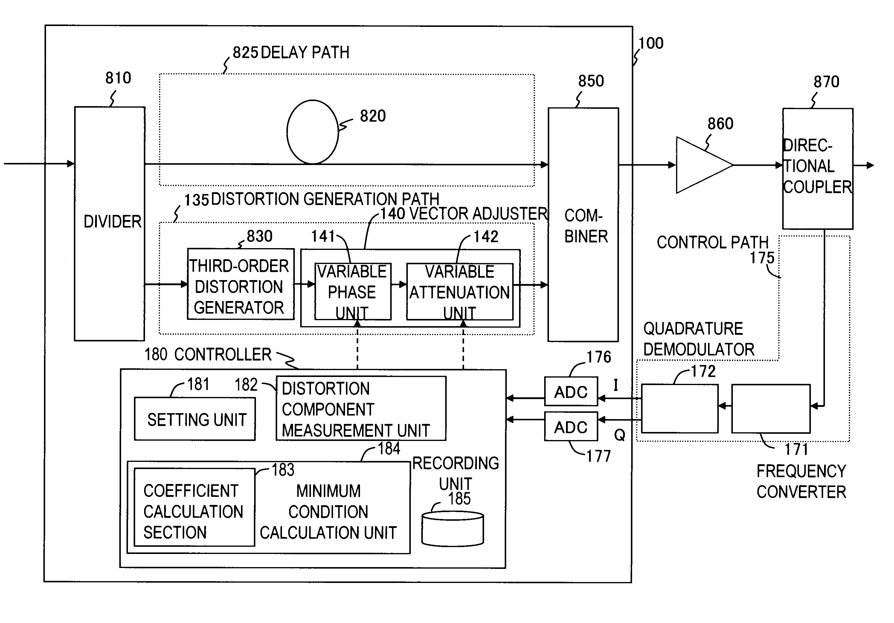
[0046]FIG. 3 shows a functional block diagram of a power series predistorter 100 of a first embodiment. The power series predistorter 100 includes a delay path 825 for delaying a signal with a delay line 820, a distortion generation path 135 having a third-order distortion generator 830 and a vector adjuster 140, a divider 810 for dividing the input signal between the delay path 825 and the distortion generation path 135, a combiner 850 for combining the output of the delay path 825 and the output of the distortion generation path 135, and a controller 180 for controlling the vector adjuster 140. An N-th order distortion generation path (N is an odd number not smaller than 3) for generating a fifth or higher odd-order distortion component may be connected in parallel to the distortion generation path 135. The vector adjuster 140 includes a variable phase unit 141 for adjusting the phase and a variable attenuation unit 142 for adjusting the amplitude. The controller 180 includes a se...

second embodiment

[0058]FIG. 5 shows a functional block diagram of a power series predistorter 200 of a second embodiment. The power series predistorter 200 differs from the power series predistorter 100 of the first embodiment in that the distortion component generated by the power amplifier is compensated for by digital signal processing. Therefore, the power series predistorter 200 differs from the power series predistorter 100 in that the digital signal is handled internally; the I component and the Q component of the digital signal are input; and the I component and the Q component of the digital signal are output. The essential portions of the power series predistorter 200, such as the functional structure and the control method, are the same as those of the power series predistorter 100. The flowchart illustrating the control method of the power series predistorter 200 is the same as that shown in FIG. 4.

[0059]The power series predistorter 200 includes a delay path 225 for delaying a signal wi...

third embodiment

[0062]FIG. 6 shows a functional block diagram of a power series predistorter 300 of a third embodiment. The power series predistorter 300 differs from the power series predistorter 200 of the second embodiment in that a frequency characteristic compensator 390 is provided instead of the vector adjuster 240. FIG. 7 shows a functional block diagram of the frequency characteristic compensator 390. FIG. 8 shows a flowchart illustrating a control method of the power series predistorter 300.

[0063]The functional structure of the power series predistorter 300 is the same as that of the power series predistorter 200 except that the frequency characteristic compensator 390 is included instead of the vector adjuster 240, and a controller 380 is provided to control the frequency characteristic compensator 390. The frequency characteristic compensator 390 includes an FFT unit 391, N complex multipliers 392-n (n is an integer from 1 to N, and N is the order of the distortion component generated i...


PUM


Abstract

A power series predistorter of the present invention includes a delay path for delaying a signal, a distortion generation path having an N-th order distortion generator and a vector adjuster, a divider for dividing an input signal between the delay path and the distortion generation path, a combiner for combining the output signal of the delay path and the output signal of the distortion generation path, and a controller for controlling the vector adjuster. The controller includes a setting unit, a distortion component measurement unit, a minimum condition calculation unit, and a recording unit. The setting unit specifies the phase or amplitude value of the vector adjuster. The distortion component measurement unit measures the distortion component of a power amplifier. The minimum condition calculation unit obtains a phase or amplitude value that minimizes the distortion component by function approximation, using the magnitude of the distortion components corresponding to three or more phase or amplitude values specified for sampling by the setting unit.

Description

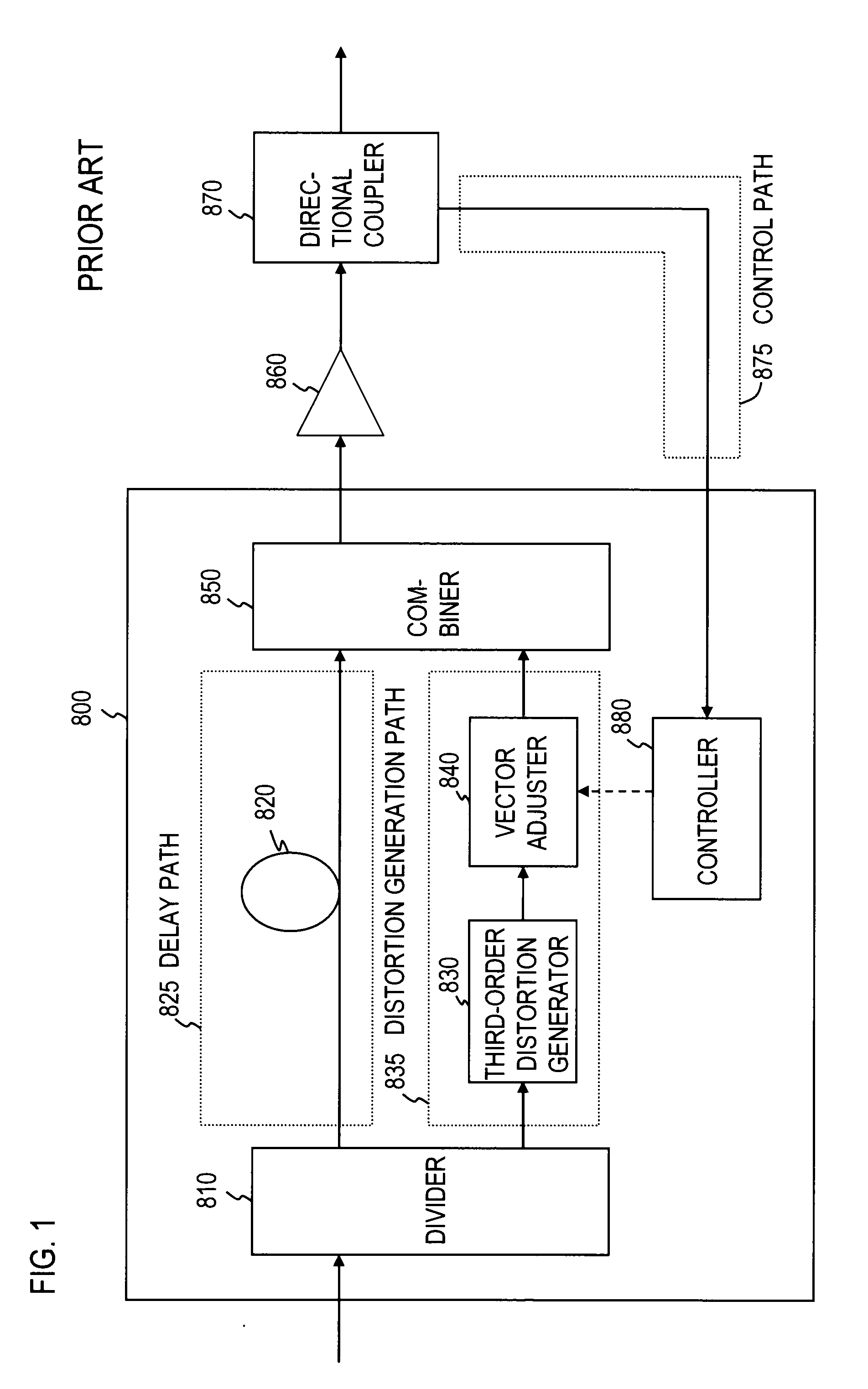
BACKGROUND OF THE INVENTION[0001]1. Field of the Invention[0002]The present invention relates to a power series predistorter for compensating for the distortion component produced by a power amplifier, and to a power series predistorter control method.[0003]2. Description of the Related Art[0004]A nonlinear distortion compensation method for a microwave transmit amplifier is a power series predistortion method. FIG. 1 shows a functional block diagram of a conventional power series predistorter 800. The power series predistorter 800 includes a delay path 825 for delaying a signal with a delay line 820, a distortion generation path 835 having a third-order distortion generator 830 and a vector adjuster 840, a divider 810 for dividing the input signal between the delay path 825 and the distortion generation path 835, a combiner 850 for combining the output of the delay path 825 and the output of the distortion generation path 835, and a controller 880 for minimizing the distortion comp...

Claims


Application Information

Patent Timeline
Patent Type & Authority Applications(United States)
IPC IPC(8): H03F1/26
CPCH03F1/3258H03F1/3247H03F1/32H04B1/62
Inventor SUZUKI, YASUNORINARAHASHI, SHOICHIOHKAWARA, JYUNYA
Owner NTT DOCOMO INC
Learn More