Method for detection of radar signals

a radar signal and detection method technology, applied in the field of wireless communication, can solve the problems of large amount of computation, synchronization errors, and identification of only those patterns, and achieve the effect of reducing the number of computations

Active Publication Date: 2010-03-11
ARRIS ENTERPRISES LLC
View PDF15 Cites 16 Cited by
  • Summary
  • Abstract
  • Description
  • Claims
  • Application Information

AI Technical Summary

Problems solved by technology

Hardware of U-NII devices considers the identification of high-energy signals on which the receiver cannot identify the proper preamble for achieving the synchronization, as “synchronization errors.” Received radar signals do not have the U-NII preamble therefore they are reported by hardware as synchronization errors.
But, interfering signals, as adjacent channel interference, interference from other systems operating in the same frequency, incorrectly received preamble due to temporary fading or due to interference from a hidden node, are also reported as synchronization errors.
This approach has the disadvantage that it can identify only those patterns that have been described in advance.
A second disadvantage of such algorithms is the fact that, for matching a large number of radar patterns, a large amount of computation has to be performed.
Detecting the existence of military radar signals is very difficult, as those systems have been designed with protection against detection.
For this reason, U-NII devices receive radar pulses as bursts of energy that cannot be decoded (high bit error rate).
A U-NII device can also receive signals with high bit error rate due to interference from adjacent channels.
The fact that signals transmitted by U-NII devices can be interpreted as radar signals causes the networks of U-NII devices to run out of resources due to adjacent channel interference.
The hardware may not be able to identify correctly the duration of such a short pulse.
Each measurement of signal strength is affected by errors that can have various causes.
When the U-NII device receives a very strong signal that cannot be decoded, the hardware generates an interrupt.
The algorithm for identifying the short pulse radar signature is very complex and requires a large amount of CPU time.
It allows fast execution, but makes difficult the identification of bursts with small number of pulses.

Method used


Image

  • Method for detection of radar signals
  • Method for detection of radar signals
  • Method for detection of radar signals

Examples


Embodiment Construction

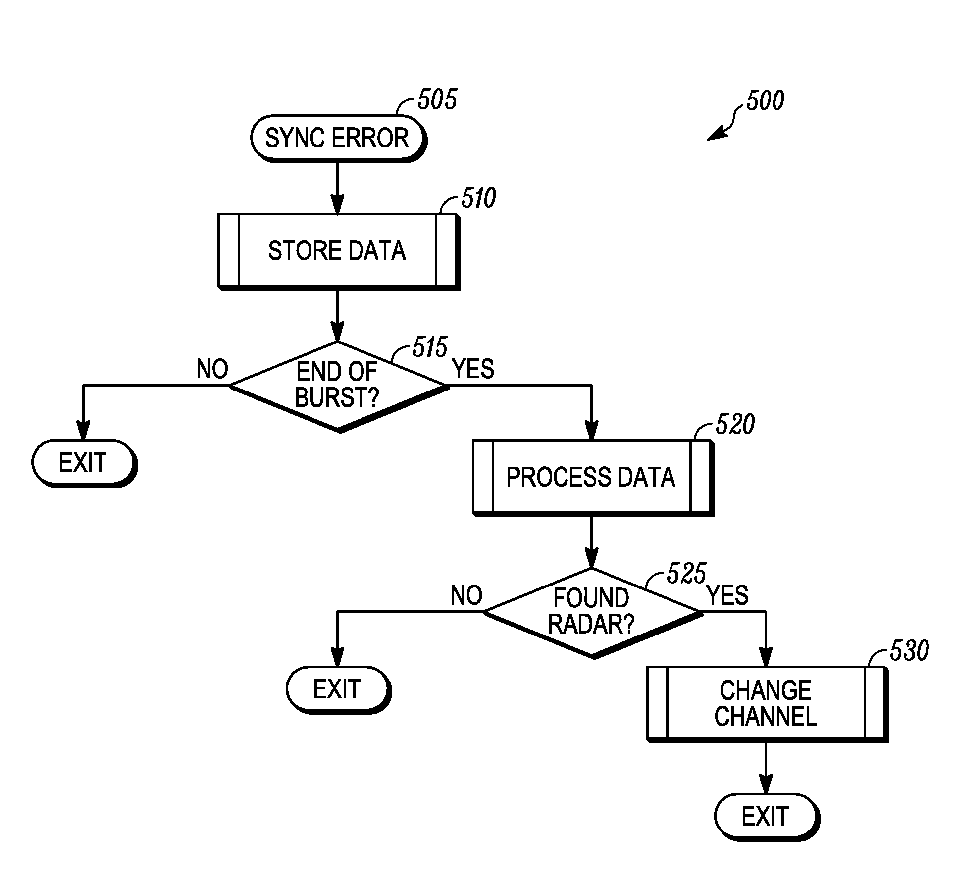
[0017]In accordance with some embodiments presented herein, a method includes collecting a set of information about received interfering signals until the End-Of-Burst (EOB) condition is identified. When the EOB is identified, the set information about the received train of interfering signals is processed. The algorithm selects the time interval between two pulses as a possible Pulse Repetition Interval (PRI) and checks if the same time interval or a multiple of it can be found between other pulses in the collected set, with some small acceptable error. Pulses matching the criteria are considered as potential radar pulses. When at least one pulse has been identified as a potential radar pulse for a number of times larger than a predefined limit, it is concluded that that pulse has been generated by a radar installation.

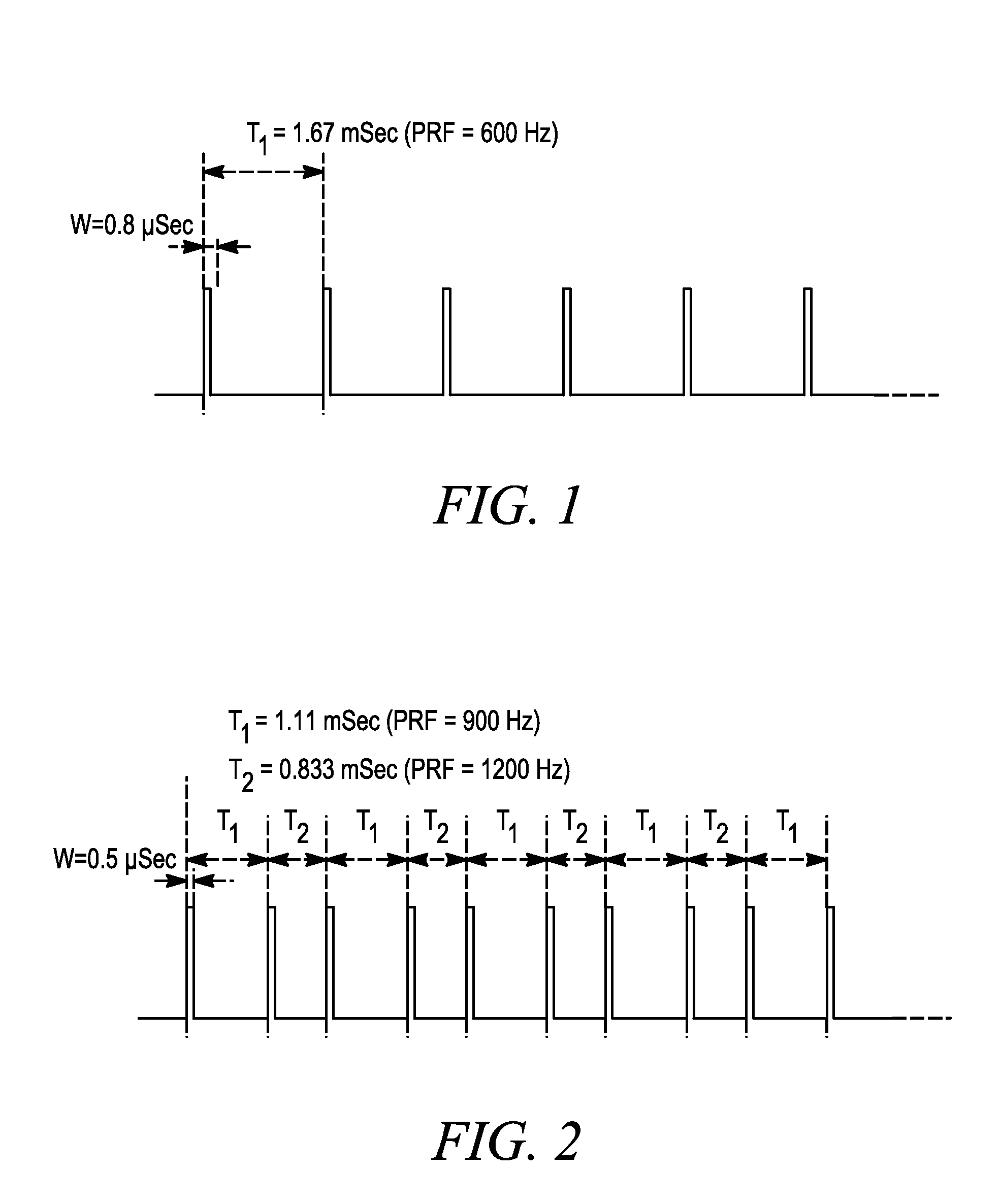
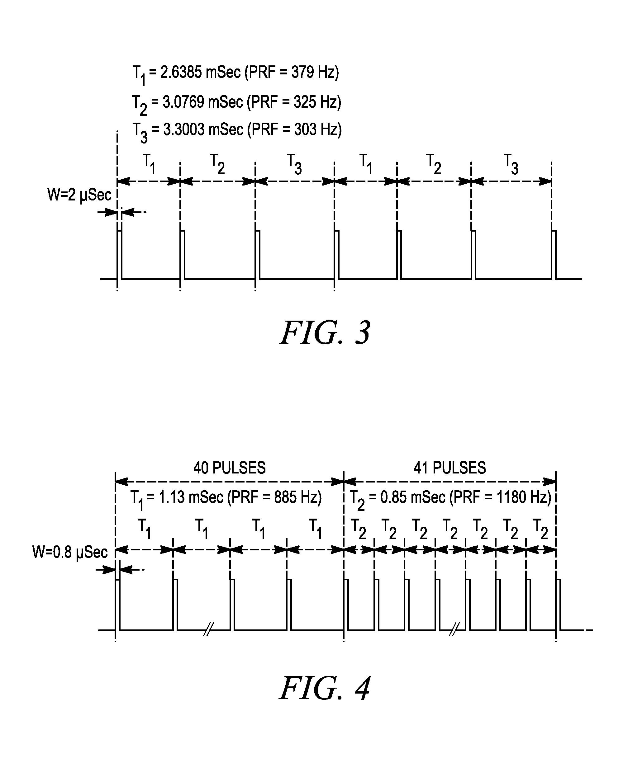
[0018]The characteristics of radar signals depend on the scope of the measurement. Radar signals are transmitted as pulses. A pulse is a continuous transmission of a...


PUM


Abstract

A method provides for identifying short radar signals in presence of interfering signals from various sources applicable to U-NII devices. The method includes collecting a set of information about received interfering signals until the End-Of-Burst (EOB) condition is identified. When the EOB is identified, the set information about the received train of interfering signals is processed. The algorithm selects the time interval between two pulses as a possible Pulse Repetition Interval (PRI) and checks if the same time interval or a multiple of it can be found between other pulses in the collected set, with some small acceptable error. Pulses matching the criteria are considered as potential radar pulses. When at least one pulse has been identified as a potential radar pulse for a number of times larger than a predefined limit, it is concluded that that pulse has been generated by a radar installation.

Description

RELATED APPLICATIONS[0001]The present application is related to and claims benefit under 35 U.S.C. § 119(e) from U.S. Provisional Patent Application Ser. No. 61 / 095,789, commonly owned with this application by Motorola, Inc., filed Sep. 10, 2008, titled “Method for Detecting In Real time Short Pulses Radar Signals”, the entire contents of which being incorporated herein by reference.FIELD OF THE DISCLOSURE[0002]The present disclosure relates generally to wireless communications and more particularly to wireless communication operation in the presence of radar signals.BACKGROUND[0003]Unlicensed National Information Infrastructure (U-NII) devices are allowed to operate in 5.15-5.35 Gigahertz (GHz) and 5.725-5.825 GHz bands if they can perform Dynamic Frequency Selection (DFS) for preventing interference with radar operations.[0004]Hardware of U-NII devices considers the identification of high-energy signals on which the receiver cannot identify the proper preamble for achieving the sy...

Claims


Application Information

Patent Timeline
Patent Type & Authority Applications(United States)
IPC IPC(8): G01S7/42
CPCG01S7/021H04K2203/18H04K3/822H04K3/226
Inventor BELCEA, JOHN M.
Owner ARRIS ENTERPRISES LLC
Why Eureka
Try Eureka