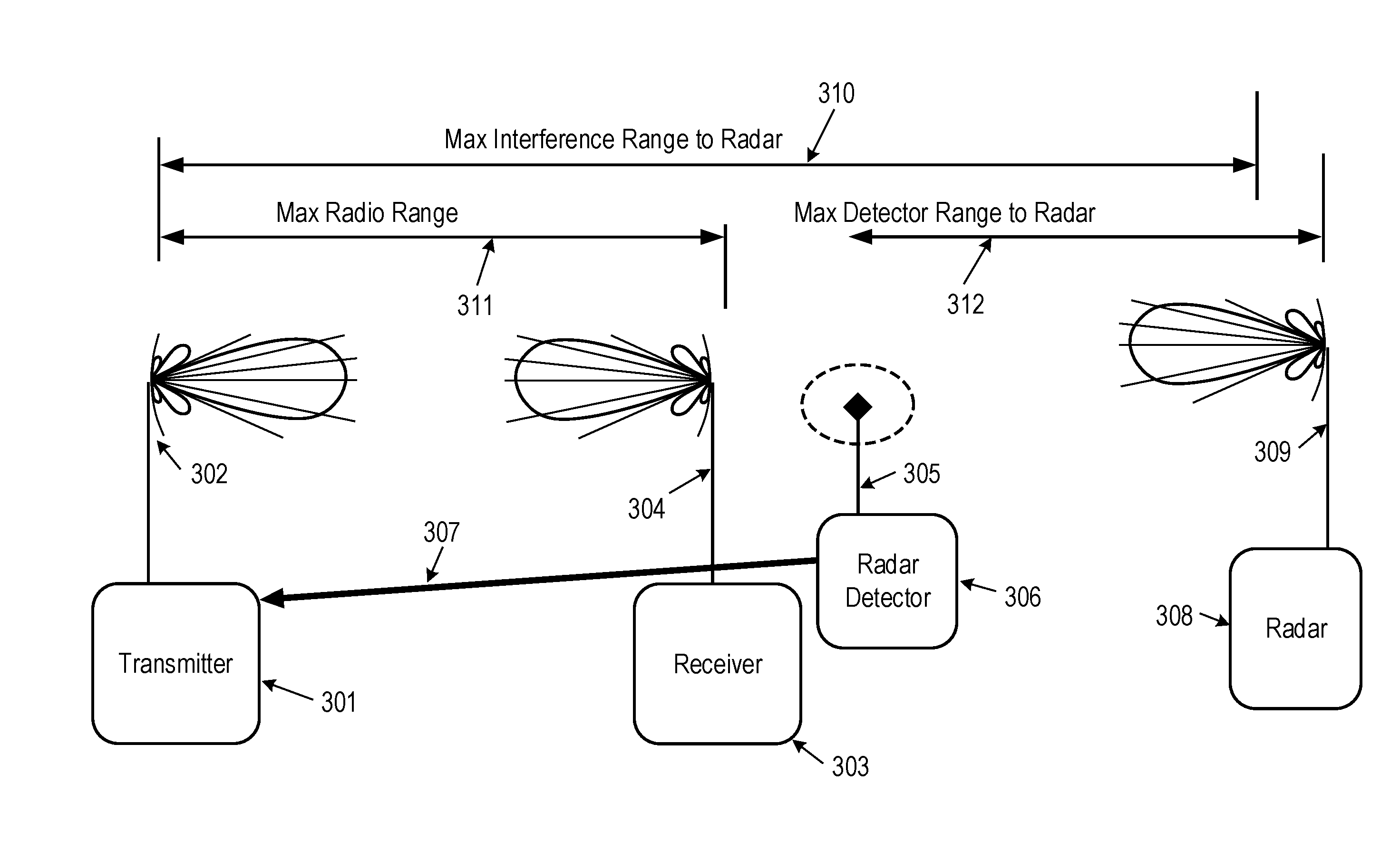
Thus the radio interferes with the radar because it cannot reliably determine that the radar is within its interference range.
That bandwidth, and a reasonable
noise figure, can result in a
noise floor of about −96
dBm.
While this theoretical limit is an improvement over the threshold of −64
dBm, it is still not low enough to prevent interruption of service to the radar (consider the exemplary
scenario in Table 1).
Experience shows that even a radar level of −64
dBm can often lack the desired reliability for detecting all the types of radars that one is required to detect.
Lowering the
detection threshold of the radar detector makes it more susceptible to false detections.
False detections can be very costly because there are regulations that require that upon getting a
radar detection, the instant channel in which the radar is detected shall be blocked for 30 minutes.
However, it would not be fully effective because the associated directionality of the antenna that accompanies the high
gain needed would prevent the detector from seeing in all directions of importance (there may be some limits on the
angle of arrival requirements in a particular situation).
The detector antenna would have to be pointed at the radar, but since there can be no prior knowledge of where the radar is or the
angle of arrival of its signal relative to the detector, this is not, in general, practical.
It is not possible to create a transmitted signal that is perfectly truncated at the bandwidth of its operating channel as there is always
some energy lying outside the channel.
Different modulation methods result in different rates of transition.
In many cases the OOBE limits are so extreme that this combination of techniques either cannot get low enough due to
system spurious, or have to be used so extensively as to make it prohibitively expensive or impractical to use in-band operation that fully exercises the parameters allowed by the in-band regulations.
Even if extensive digital and analog filtering is used, a very small amount of spectral regrowth or spurious can
impact passing the extreme filtering requirements that regulations impose.
Therefore, much of this 100 MHz band essentially becomes unusable at this
power level.
Even at lower power levels, it is very difficult to make use of more than half the band.
Even if the filtering at
baseband exceeds this value, by the time the signal is modulated and reaches the antenna, the up-conversion spurious and spectral regrowth reduces the effect of the
baseband filtering.
Designs often require substantial power
amplifier back-off to reduce the spectral regrowth and spurious modulation, yet experience teaches us that there is still not enough suppression to utilize the major part of the band at the full allotment of EIRP.
Still, with all this overprotection, if the operating transmitter is less than 6.3 km away from the victim, the victim's
receiver will be affected.
The pre-selection of this level both creates an unnecessary burden for the operating transmitter and only partly solves the victim's problem.
For a more modest case of lower receive
antenna gain on the equipment that is being protected, the wasted protection is even higher.
Furthermore, the protected equipment is not operating all the time and the in-band emitter that is creating the OOBE isn't operating all the time.
When incorporating operating percentages, the amount of wasted protection adds up to a very high percentage.
However, for many types of equipment, there is no way to know a priori where the protected equipment is located or when it will be operating.

