System and method of using absorber-walls for mutual coupling reduction between microstrip antennas or brick wall antennas

a technology of absorber wall and microstrip antenna, which is applied in the direction of antenna details, instruments, antennas, etc., can solve the problems of leakage from a transmitting element to the return path of one or more neighboring antenna elements, limit the time of the radar pulse, and limited detection sensitivity

Inactive Publication Date: 2008-09-23
COBHAM DEFENSE ELECTRONICS SYST CORP
View PDF9 Cites 86 Cited by
  • Summary
  • Abstract
  • Description
  • Claims
  • Application Information

AI Technical Summary

Benefits of technology

[0010]In a preferred embodiment of the invention, a microstrip patch antenna has radio frequency (RF) absorbing material placed between neighboring antenna elements to reduce the mutual coupling leakage signals.
[0011]The horizontal size of a microstrip patch antenna element may be reduced by capacitive loading by, for instance, providing a back cavity with controlled opening. This reduction in horizontal size relative to the size of a typical microstrip patch antenna element operating at a comparable wavelength, effects some reduction in mutual coupling. The size reduction also creates sufficient space between adjacent patch antenna elements to allow enough RF absorbing material to be placed there to further reduce mutual coupling.
[0013]In this preferred embodiment, there is a slight reduction in the power output of the antenna due to the absorbing material but no appreciable distortion of the antenna radiation patterns. Despite the slight reduction in power output, the overall sensitivity of a pulsed radar system using such an antenna in detecting small objects at a large distance is significantly improved because of the ability to simultaneously transmit and receive, which allows significantly longer pulses to be used.

Problems solved by technology

In a pulsed radar system used for detecting the presence of small objects at large distances, the detection sensitivity is limited by the amount of energy in the reflected pulse (also known as the return pulse) when it reaches the receiving antenna.
There is, however, a limit to how long the radar pulse can be made.
Furthermore, a transmission antenna can only be exactly impedance matched at a narrow band of frequencies, so that in any real radar system having a finite bandwidth signal, a small fraction of the transmitted signal is reflected back from the antenna along the radar's receive path in what is known as a return loss leakage signal.
If the radar system has multi-element, patch antennas, something that is highly desirable for radar beam steering, there is the additional problem of leakage from a transmitting element to the return path of one or more neighboring antenna elements, known as leakage due to mutual coupling.
As a result, the length of the pulse that can be used in such systems is limited to the time an RF pulse takes to reach and return from the target.
In many practical situations, such as radar systems on aircraft or automobiles, it is not possible to separate the receiving and transmitting antenna sufficiently for them to operate at the same time.

Method used


Image

  • System and method of using absorber-walls for mutual coupling reduction between microstrip antennas or brick wall antennas
  • System and method of using absorber-walls for mutual coupling reduction between microstrip antennas or brick wall antennas
  • System and method of using absorber-walls for mutual coupling reduction between microstrip antennas or brick wall antennas

Examples


Embodiment Construction

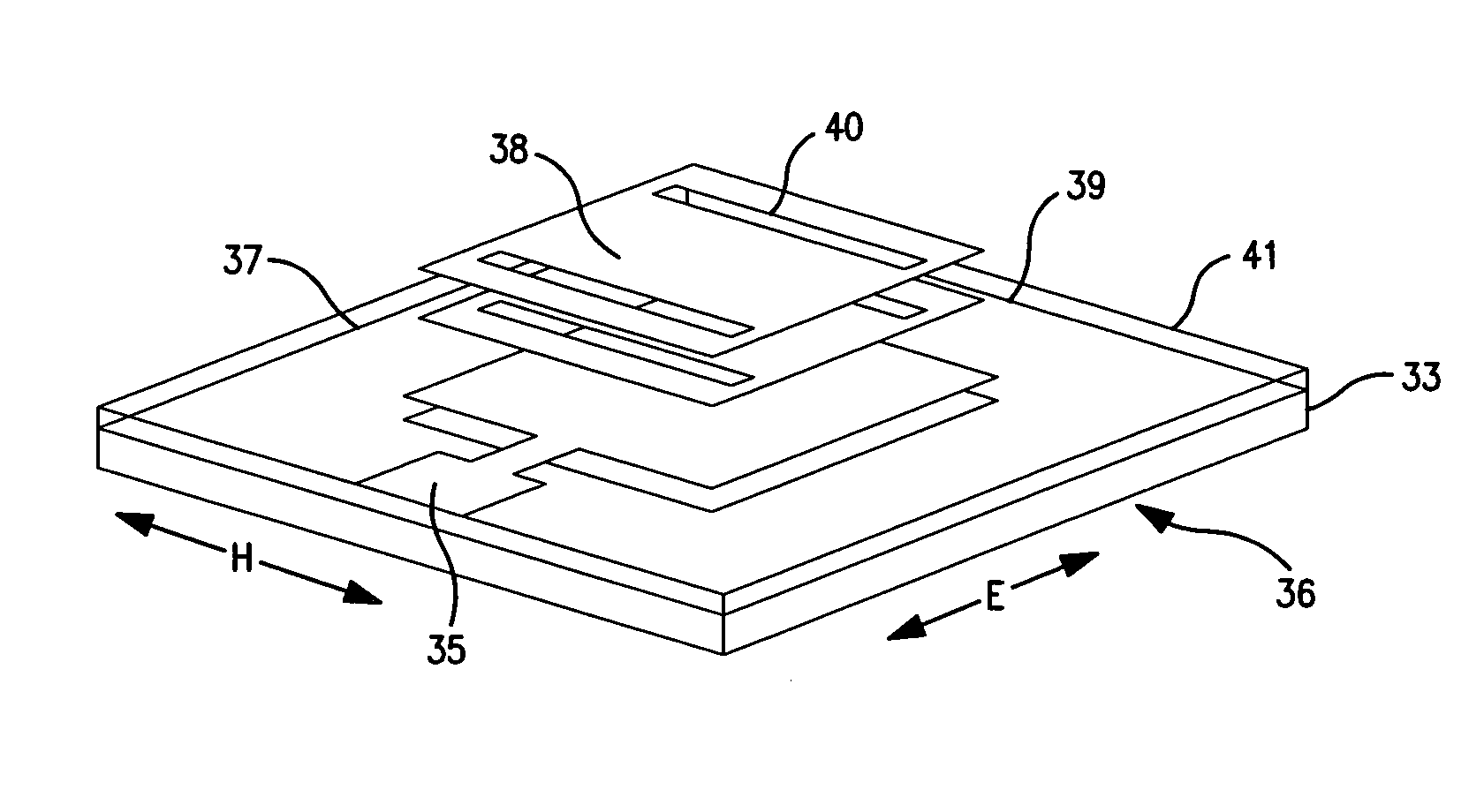
[0035]The present invention provides a system, method and apparatus for reducing antenna internal losses, including any finite return loss or mutual coupling losses. The system, method and apparatus are particularly suitable for reducing the finite return and mutual coupling loses in a stacked microstrip patch antenna so that is suitable for use as a microwave or radio frequency (RF) phased array antenna.

[0036]In a preferred embodiment that is suitable for use in radar applications, a compact, high directivity antenna having a multiplicity of transmitting elements has the mutual coupling losses between these elements reduced by placing a ring of microwave or RF absorbing material between the elements. In a further embodiment of the invention metal elements may also be used as part of the RF absorbing ring separating the antenna elements.

[0037]The horizontal size of a microstrip patch antenna element may be reduced by capacitive loading by, for instance, providing an underlying back ...


PUM


Abstract

A multi-element antenna with sufficiently small return loss and mutual coupling signals to allow the simultaneous transmission of powerful radar signals and the reception of faint target return signals. The microstrip patch antenna has radio frequency absorbing material place between neighboring antenna elements to reduce the mutual coupling leakage signals.

Description

FIELD OF THE INVENTION[0001]The present invention relates to antennas for use in pulsed radar applications, and more particularly to co-located microwave radar antennas capable of simultaneously transmitting and receiving pulsed signals.BACKGROUND OF THE INVENTION[0002]Pulsed radar is a well known technique for detecting objects at a distance. A high-power radio frequency (RF), pulsed signal is transmitted in the direction of a target object, and the signal reflected off the object is detected by a sensitive receiver. The distance to the target may be determined by measuring the time delay between transmitting the signal and receiving signal reflected from the target. A velocity of the target may also be determined by measuring any frequency change of the reflected signal.[0003]In a pulsed radar system used for detecting the presence of small objects at large distances, the detection sensitivity is limited by the amount of energy in the reflected pulse (also known as the return puls...

Claims


Application Information

Patent Timeline
Patent Type & Authority Patents(United States)
IPC IPC(8): H01Q17/00
CPCH01Q1/521H01Q17/00H01Q1/526
Inventor CHANNABASAPPA, ESWARAPPAEGRI, ROBERT
Owner COBHAM DEFENSE ELECTRONICS SYST CORP
Why Eureka
Try Eureka