In-plane switching electrophoretic colour display

a colour display and in-plane switching technology, applied in the field of electrophoretic color display panels, can solve the problems of difficult to achieve the controllability of the distribution of different sets of charged particles in such an arrangement, and achieve the effect of improving electrophoreti

Inactive Publication Date: 2010-03-11
KONINKLIJKE PHILIPS ELECTRONICS NV
View PDF8 Cites 63 Cited by
  • Summary
  • Abstract
  • Description
  • Claims
  • Application Information

AI Technical Summary

Benefits of technology

[0005]There is therefore a need for an improved electrophoretic color display panel, more specifically an electrophoretic color display that overcomes or at least alleviates the problem with the positioning of electrodes in a cell for such an electrophoretic display panel.

Problems solved by technology

However, it is not straightforward to achieve controllability of the distribution of different sets of charged particles in such an arrangement.

Method used


Image

  • In-plane switching electrophoretic colour display
  • In-plane switching electrophoretic colour display
  • In-plane switching electrophoretic colour display

Examples


Embodiment Construction

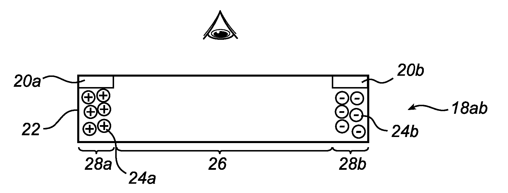
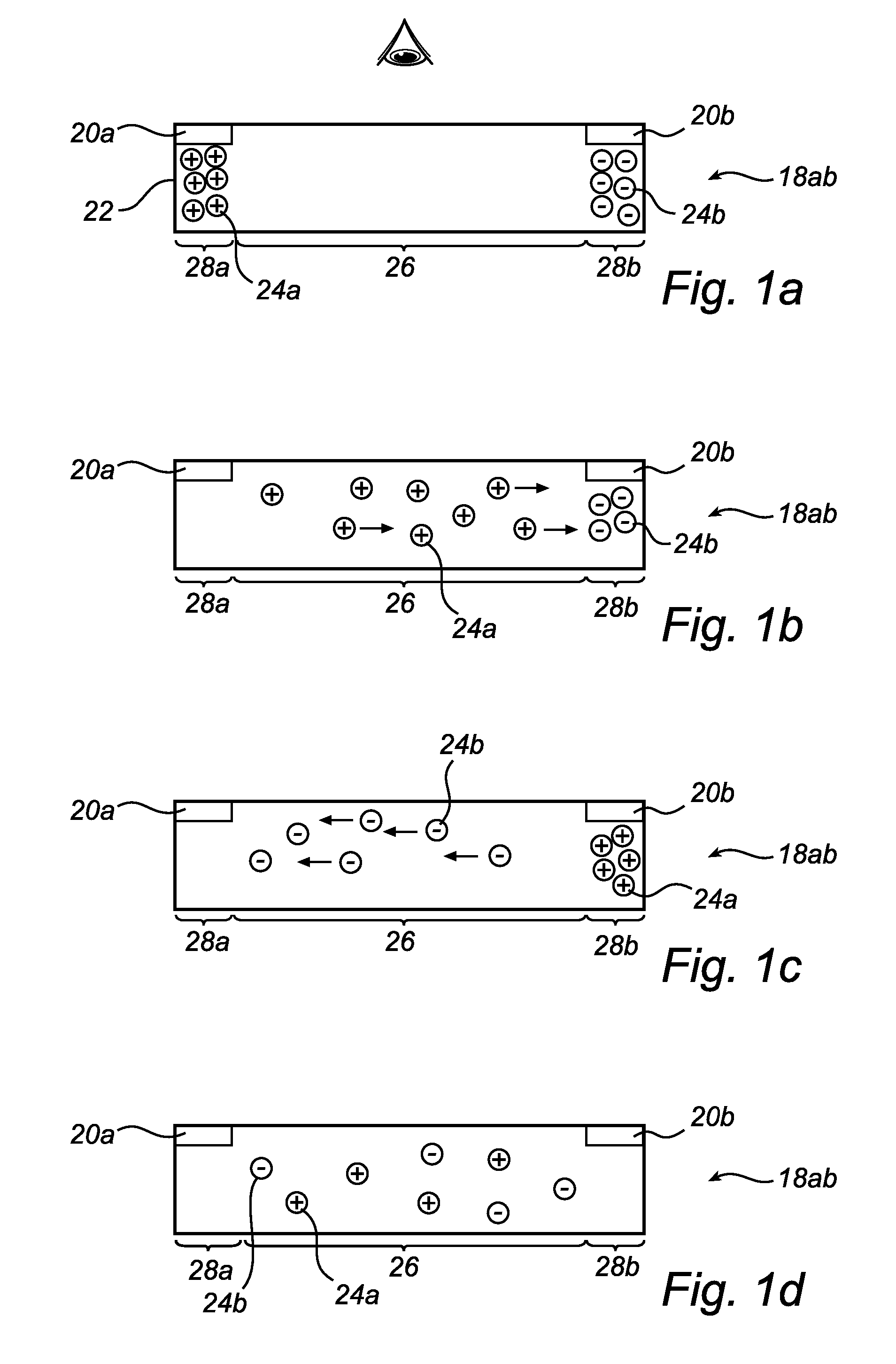
[0024]Referring to the drawings and to FIG. 1a-1d in particular, there is depicted a layer cavity 18ab for use in a color subtractive electrophoretic display according to an embodiment of the present invention. In FIG. 1, the layer cavity 18ab comprises two addressable control electrodes 20a and 20b. The electrodes 20a and 20b are preferably placed at opposite corners of the layer cavity 18ab, in collector areas 28a, 28b, outside of the viewing area 26 of the pixel 10. Alternatively, they can be placed along opposite side walls 22 of the layer cavity 18ab. The suspension of layer cavity 18ab further comprises two different sets of charged particles 24a and 24b, which except for color (e.g. optical property) differ in at least one other control property. In this example, one set of particles comprise cyan particles 24a having a positive charge and high mobility, while the other set of particles comprise yellow particles 24b having a negative charge and low mobility. By appropriately ...


PUM

PropertyMeasurementUnit
angleaaaaaaaaaa
optical propertyaaaaaaaaaa
optical propertiesaaaaaaaaaa

Abstract

The invention relates to an electrophoretic color display panel, the display panel comprising at least one pixel (10, 12), the at least one pixel (10, 12) comprising a layer cavity (18ab) containing a suspension with a first set of charged particles (24a) having a first optical property and a second set of charged particles (24b) having a second optical property, and a pair of control electrodes (20a, 20b) arranged adjacent to the layer cavity (18ab), such that charged particles (24a, 24b) are essentially in-plane displaceable in an in-plane direction within the layer cavity (18ab) upon application of a control voltage over the electrode pair, wherein the in-plane distribution of charged particles (24a, 24b) having first and second optical properties in the layer cavity (18ab) depends on at least one of a differing control property additional to any polarity difference of the charged particles (24a, 24b) for each set of charged particles, or at least one additional electrode arranged adjacent to the layer cavity, wherein the electrode pair (20a, 20b) and the at least one additional control electrode are arranged essentially outside of a viewing area (26) of the at least one pixel (10, 12), such that a composite optical property of at least a portion of the at least one pixel (10, 12) is controllable. According to the invention, the control electrodes will be arranged at essentially the outer ends, or arranged in-plane, at a peripheral, of a prolonged layer cavity, such that the particles move in an in-plane direction within the layer cavity when the control voltage is applied. This facilitates the handling of the pixel since the layer cavity can be reached from essentially the outside of the pixel. Another advantage is that since only a minor part of the pixel area has to be covered with an electrode material the total transmission and thus the brightness of the pixel can be optimized.

Description

FIELD OF THE INVENTION[0001]The invention relates to an electrophoretic color display panel for displaying an image.BACKGROUND OF THE INVENTION[0002]An example of an electrophoretic color display panel is disclosed in U.S. Pat. No. 6,680,726. More precisely, U.S. Pat. No. 6,680,726 relates to a transmissive color electrophoretic display incorporated with a backlight. The display has a plurality of laterally adjacent pixels. Each pixel is comprised of two or more cells which are vertically stacked, one directly above the other on the horizontal surface of a panel located at the rear or bottom of the stacks. Each cell in a stack also has laterally adjacent like cells which together form a layer of cells in the display. Between each cell, there is a light-transmissive window. The cells contain a light-transmissive fluid and charged particles that can absorb a portion of the visible spectrum, with each cell in a stack containing particles having a color different from the colors of the ...

Claims


Application Information

Patent Timeline
Patent Type & Authority Applications(United States)
IPC IPC(8): G09G3/34G06F3/038G02F1/167G02F1/1677
CPCG02F1/134363G02F1/13473G02F2203/34G02F2001/1678G02F1/167G02F1/1677G02F1/16762G02F1/16761
Inventor LENSSEN, KARS-MICHIEL HUBERTBAESJOU, PATRICK JOHNVAN DELDEN, MARTINUS HERMANUS WILHELMUS MARIAROOSENDAAL, SANDER JURGENSTOFMEEL, LEON WILHELMUS GODEFRIDUSVERSCHUEREN, ALWIN ROGIER MARTIJN
Owner KONINKLIJKE PHILIPS ELECTRONICS NV
Why Eureka
Try Eureka