
Animatable Graphics Lighting Analysis Reporting

a lighting analysis and animation technology, applied in the field of computer graphics, can solve the problems of not being able to effectively pull up the lighting values associated with the surface, unable to view the aggregate of the lighting values, and end users can only view the lighting values one point at a time, so as to achieve the effect of easy observation of the lighting values and easy viewing of the associated lighting values

Active Publication Date: 2010-03-11
AUTODESK INC
View PDF42 Cites 5 Cited by
  • Summary
  • Abstract
  • Description
  • Claims
  • Application Information

AI Technical Summary

Benefits of technology

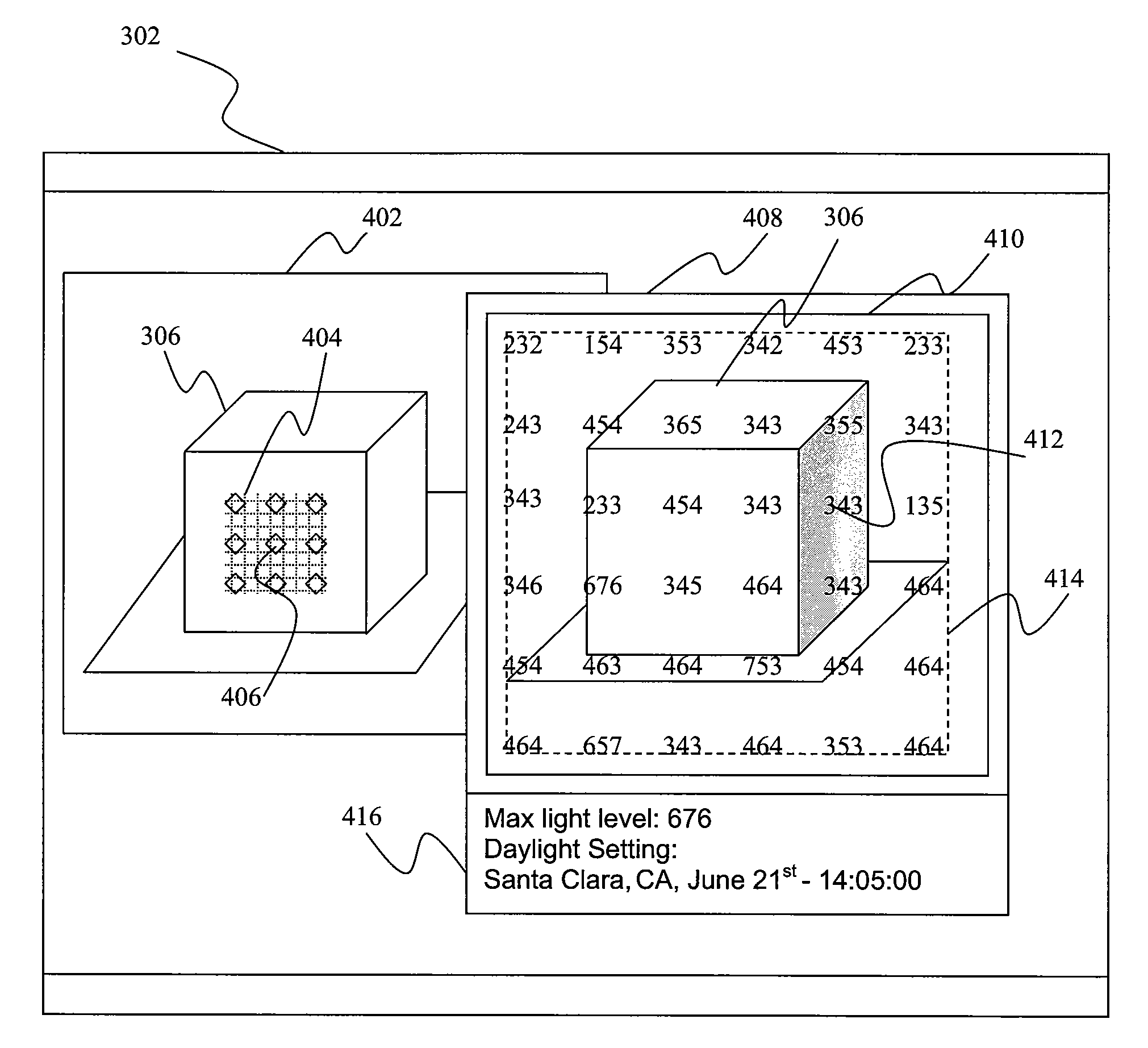
[0009]One advantage of the disclosed method is that the computed lighting values may be superimposed with an overlay grid on the graphics model, allowing the end-user to easily view the lighting values associated with the graphics model. In addition, since the lighting values associated with the light meter may be computed for every frame that includes the graphics model, the effects of a varying light source on the graphics model can be easily observed by way of the overlay grid with computed lighting values rendered on top of the graphics model.

Problems solved by technology

However, the end-user can only view these lighting values one point at a time, usually by moving the cursor over the graphics scene.
The end-user is not able to see the aggregate of the lighting values that were computed across the 3-D scene.
However, there is no effective way to pull up these values associated with those surfaces.
In addition, since lighting values are computed one frame at a time, there usually is no efficient way to see the varying lighting values frame-over-frame, as the lighting changes.

Method used


Image

  • Animatable Graphics Lighting Analysis Reporting
  • Animatable Graphics Lighting Analysis Reporting
  • Animatable Graphics Lighting Analysis Reporting

Examples


Embodiment Construction

[0022]In the following description, numerous specific details are set forth to provide a more thorough understanding of the present invention. However, it will be apparent to one of skill in the art that the present invention may be practiced without one or more of these specific details. In other instances, well-known features have not been described in order to avoid obscuring the present invention.

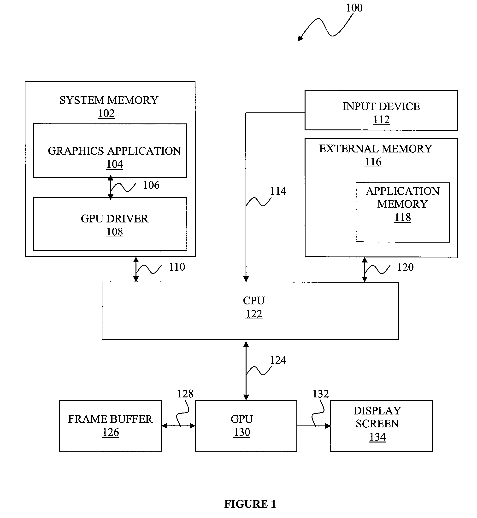
[0023]FIG. 1 illustrates a computer system 100 configured to implement one or more aspects of the present invention. As shown, the computer system 100 includes a system memory 102, an input device 112, an external memory 116, a central processing unit (CPU) 122, a frame buffer 126, a graphics processing unit (GPU) 130 and a display screen 134. The system memory 102 includes a graphics application 104 and a GPU driver 108. The system memory 102 is a memory space, usually a random access memory, that temporarily stores software programs being used in the system 100 at any given time. The ...


PUM


Abstract

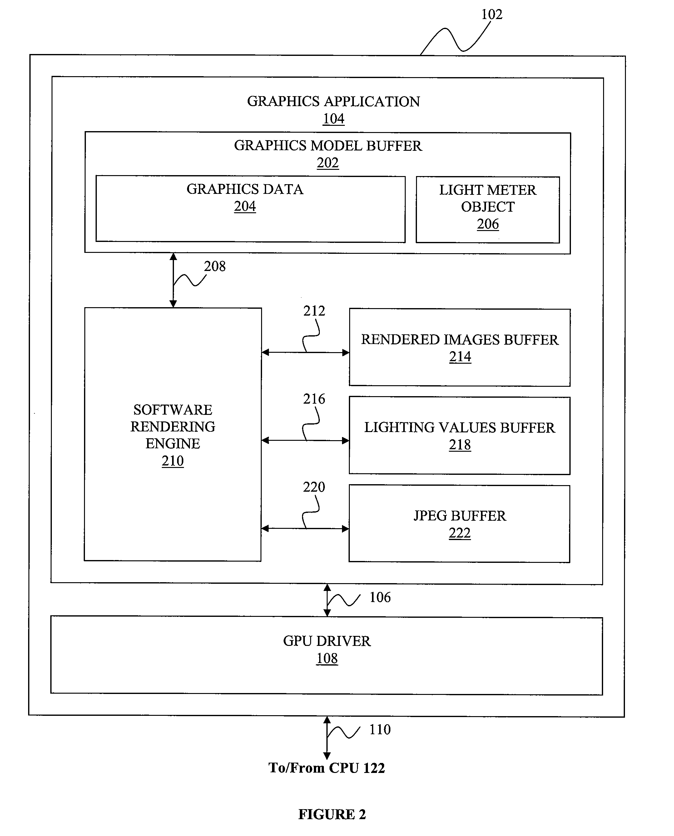
One embodiment of the invention sets forth a mechanism for displaying lighting values associated with a 3-D graphics model by superimposing an overlay grid with lighting values on the 3-D graphics model. A software rendering engine computes lighting values for each frame that includes the 3-D graphics model, where each frame may have different lighting settings. An overlay grid with lighting values may be superimposed on an area defined by a light meter on the 3-D graphics model. The lighting values on the overlay grid are associated with the light meter and may vary frame-over-frame. In another embodiment, a JPEG image with a superimposed overlay grid with per-pixel lighting values covering a 3-D graphics model is generated for each frame that includes the 3-D graphics model. These JPEG images may be displayed on the screen and stored to an external memory.

Description

BACKGROUND OF THE INVENTION[0001]1. Field of the Invention[0002]The present invention relates generally to the field of computer graphics and, more specifically, to animatable graphics lighting analysis reporting.[0003]2. Description of the Related Art[0004]In graphics design, one parameter that affects the final rendered image is the lighting that illuminates different surfaces of the graphics objects within the image at potentially different intensities. Lighting values are typically computed using sophisticated mathematical formulas involving factors like the positions of different objects relative to the light source(s) as well as the intensity of those light sources. Further, with a dynamic light source, i.e. a light source that has varying intensity and position over time, like daylight, lighting values associated with the different surfaces will vary over time too. Users of graphics modeling and creation software need to be able to inspect lighting values across the different...

Claims


Application Information

Patent Timeline
IPC IPC(8): G06T15/50
CPCG06T15/50
Inventor BRETON, PIERRE-FELIXSIMPSON, KELCEYZYRACKI, MICHAEL
Owner AUTODESK INC
Learn More