Communication System

a communication system and electromagnetic field technology, applied in the field of electromagnetic field communication systems, can solve the problems of gate voltage straying from the fet ground, inconvenient operation, complex structure of the receiver, etc., and achieve the effect of simple receiver configuration and stable receiving action

Inactive Publication Date: 2010-03-11
KAISER TECHKK
View PDF2 Cites 127 Cited by
  • Summary
  • Abstract
  • Description
  • Claims
  • Application Information

AI Technical Summary

Benefits of technology

[0026]As mentioned above, the present invention can provide stable receiving action in the communication system, which us

Problems solved by technology

Consequently, the receiver will be of complicated structure and more costly.
On the other hand, when the technology to install the FET with a gate connected with the electrode located in the electric field in the vicinity of the human body, the gate voltage is strayed from the FET ground so that it's operating range is not ass

Method used


Image

  • Communication System
  • Communication System
  • Communication System

Examples


first embodiment

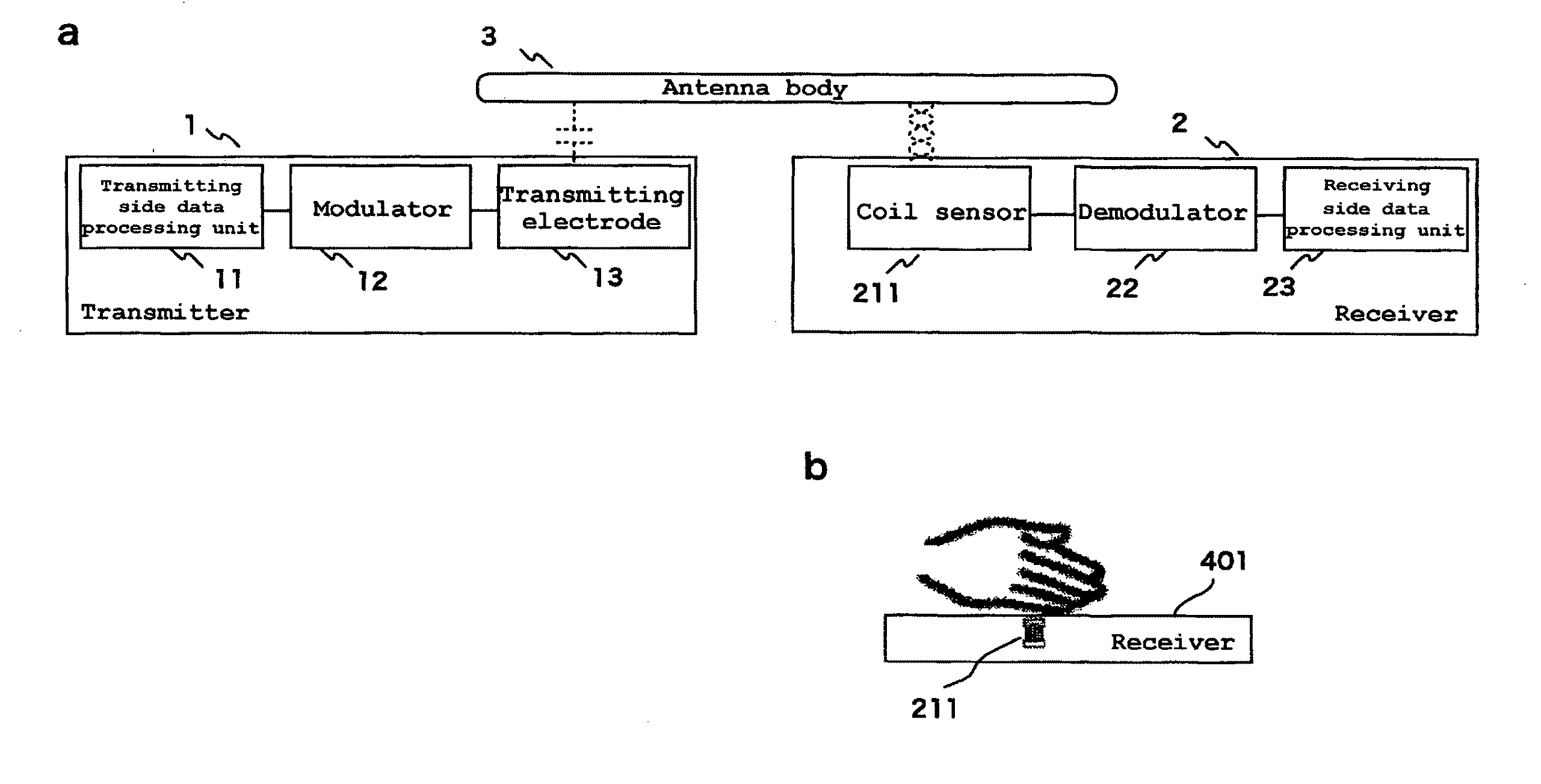
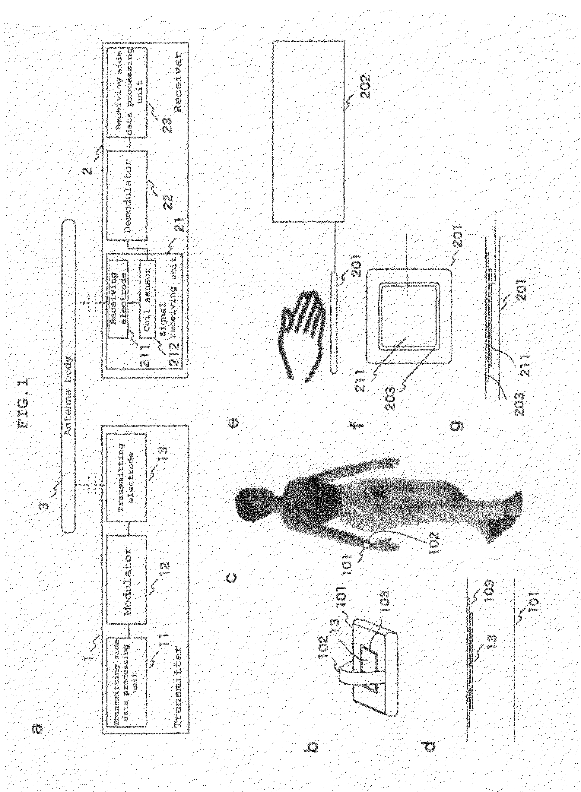
[0028]To begin with, this invention is explained. FIG. 1a shows the functional configuration of the communication system related to the embodiment of the present invention.

[0029]As shown in FIG. 1a, the communication system is configured by the transmitter 1 and the receiver 2, which communicate via the antenna body 3.

[0030]Also, the transmitter 1 has the transmitting side data processing unit 11, which generates communication information, which is to be transmitted to the receiver 2, the modulator 12, which modulates communication information and outputs it as transmission signals, and the transmitting electrode 13, which applies transmission signals to the antenna body 3. The receiver 2 has the signal receiving unit 21, which detects the strength of electric field induced by the antenna body 3 and outputs it as received signals, the demodulator 22, which demodulates the received signals into communication information and the receiving side data processing unit 23, which processes ...

second embodiment

[0051]the present invention is explained below.

[0052]FIG. 4a shows the functional configuration of the communication system of this embodiment.

[0053]As shown in the figure, the communication system relating to the second embodiment of the present invention has the same configuration as that of the abovementioned first embodiment except that the receiving electrode 211 of the receiver 2 is removed.

[0054]FIG. 4b shows the external configuration of the receiver 2.

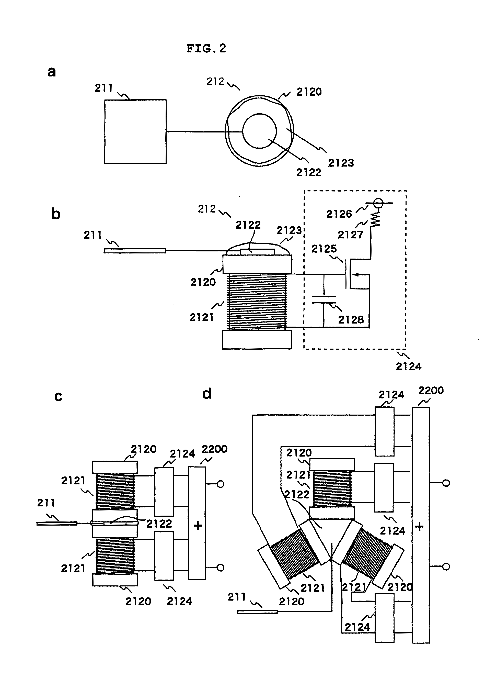
[0055]As shown in the figure, the receiver 2 has a configuration that the coil sensor 212, the demodulator 22 and the receiving side data processing unit 23 are housed in the single case 401. And just under the top surface of such case 401, the coil sensor 212 is placed such that the axis of the coil 2121 becomes perpendicular to the surface.

[0056]With such receiver 2, when a human hand is held over the case 401, the electro-magnetic field in the vicinity of the human body acts upon the coil sensor 212 placed just under the to...

third embodiment

[0060]the present invention is explained below.

[0061]FIG. 5a shows the functional configuration of the communication system of the embodiment of the present invention.

[0062]As shown in the figure, the communication system according to this embodiment is equipped with the magnetic field detection antenna 501 and the magnetic field strength detecting unit 502 in the signal receiving unit 21 of the receiver 2, in place of the receiving electrode 211 and the coil sensor 212 of the communication system of the aforementioned first embodiment.

[0063]FIG. 5b shows the appearance of the receiver 2.

[0064]As illustrated in the figure, the receiver 2 has the antenna panel 503, which houses the magnetic field detection antenna 501, and the receiver chassis 504, which houses the magnetic field strength detecting unit 502, the demodulator 22 and the receiving side data processing unit 23. The magnetic field detection antenna 501 is of magnetic type, such as loop antenna, for example. As shown in th...


PUM


Abstract

Stable receiving action is achieved with a receiver of simpler configuration.
When a human hand is held over the panel unit 201, the electric field in the vicinity of the human body is coupled to the sensor electrode 2122 of the coil sensor 212 from the receiving electrode 211 of the panel unit 201, and alternate current is generated at the sensor electrode 2122. This alternate current then induces a magnetic flux inside the central opening of the coil 2121 in proportion to the strength of the electric field in the vicinity of the human body. Depending on the changes in this magnetic flux, electric current passes through the coil 2121. The electric current passing through the coil 2121 is converted by the electric current detecting circuit 2124 of the coil sensor 212 to voltage signals and transmitted as received signals to the demodulator 22. As a result, the received signals corresponding to the electric field in the vicinity of the human body, namely the transmission signals applied by the transmitter 1 to the human body, are obtained.

Description

TECHNICAL FIELD[0001]The present invention relates to a communication system using electro-magnetic field for communication. Particularly, it relates to a communication system, which communicates by using electro-magnetic field induced in the human body.BACKGROUND ART[0002]The communication systems known as using an electro-magnetic field induced in the human body include a communication systems comprising a transmitter, in which voltage signals generated by modulating communication information is applied to the human body by capacitance coupling to induce an electric field in the vicinity of the human body, and a receiver, in which the strength of the electric field induced by the human body is detected and the strength of the electric field is demodulated into communication information (refer to patent documents 1, 2 and 3).[0003]In these communication systems the electric field strength in the receiver is detected by coupling the electric field in the vicinity of the human body w...

Claims


Application Information

Patent Timeline
IPC IPC(8): H04B5/00H01Q7/08
CPCH01Q1/2216H04B5/0018H04B17/0057H04B5/0087H04B5/0043G01R29/0878H04B5/02H04B13/005H04B17/23H04B17/318H04B13/02
Inventor KATO, YASUO
Owner KAISER TECHKK
Why Eureka
Try Eureka