Method for the determination of a nacelle-inclination

Inactive Publication Date: 2010-03-11
SIEMENS AG
1 Cites 19 Cited by

AI-Extracted Technical Summary

Problems solved by technology

The forces caused by acceleration of the nacelle will be part of the acce...

Method used

[0029]For the calibration purposes the position of the nacelle and of their wind-blades too is changed in t...

Benefits of technology

[0017]The inventive method leads to an improved determination of the nacelle-inclination, with...

Abstract

In one aspect, a method for the determination of a nacelle-inclination is provided. A first difference-signal is formed from the difference of a measured nacelle acceleration and an offset-value from a calibration. A second difference-signal is formed from a difference of the first difference-signal and a feedback signal. A first sum-signal is formed from adding an integrated second difference-signal with the product of the second difference signal and a factor. A second sum signal is formed from adding an integrated first sum-signal with the product of the first-sum-signal and the factor. A corrected signal is formed by a product of the second sum-signal and an equivalent tower height. A first nacelle-signal is formed by the arc-tangent of the corrected signal. A nacelle inclination is obtained from filtering the first nacelle-signal by a low-pass-filter. The feedback-signal is formed by multiplying the acceleration of gravity with the sine of the first nacelle-signal.

Application Domain

Wind motor controlDigital data processing details +16

Technology Topic

NacelleEngineering +5

Image

  • Method for the determination of a nacelle-inclination
  • Method for the determination of a nacelle-inclination
  • Method for the determination of a nacelle-inclination

Examples

  • Experimental program(1)

Example

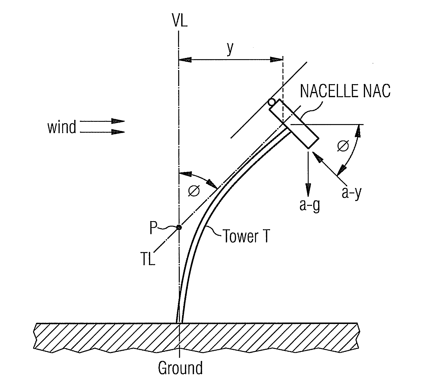
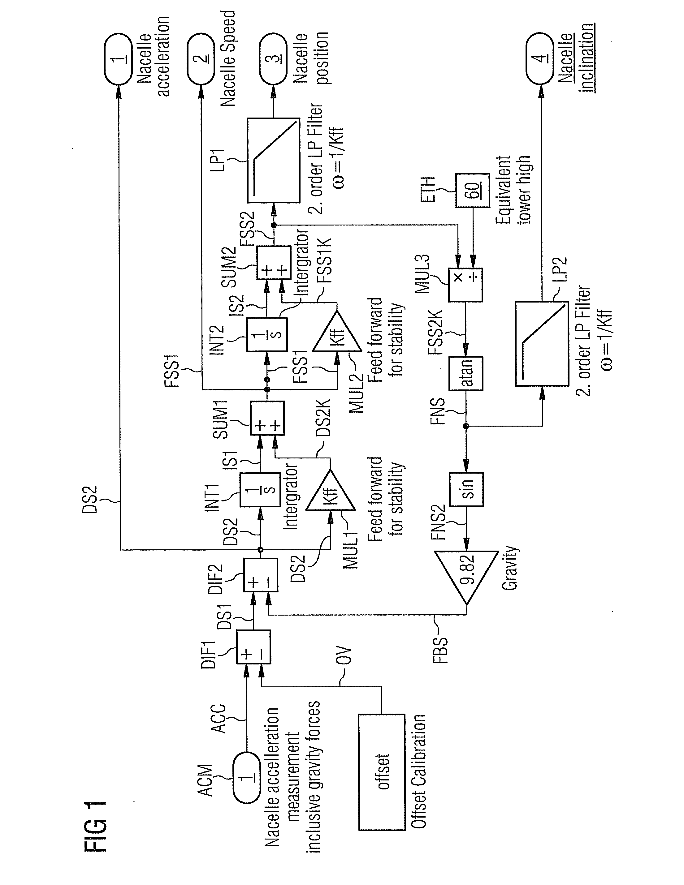
[0026]According to the invention an acceleration ACC of a nacelle is measured with help of an accelerometer ACM, which is mounted—for example—within or at the nacelle. A conventional two-axis-accelerometer can be used as accelerometer.
[0027]The measured acceleration is brought as first input-signal to a first difference-element DIF1.
[0028]An offset-value OV, which is necessary for calibration, is brought as second input-signal to the first difference-element DIF1.
[0029]For the calibration purposes the position of the nacelle and of their wind-blades too is changed in that kind, that the wind-forces on the nacelle are minimized and therefore the inclination is also minimized.
[0030]It is also possible, to use estimated, pre-calculated values as offset-value OV. The offset-value OV can be calculated based on mean values of the accelerometer-output, when the rotating propeller-blades of the nacelle are stopped as described above.
[0031]It is also possible to calculate the offset-value OV based on an “online closed loop calibration”. Due to this, the offset-value OV is changed until a mean value of nacelle-position and nacelle-inclination is equal to expected values. The expected values form a function of turbine power on the one hand and of pitch position of the other hand.
[0032]The first difference-element DIF1 calculates a difference between the measured acceleration ACC and the offset-value OV, resulting in a first difference-signal DS1.
[0033]The first difference-signal DS1 is brought as first input-signal to a second difference-element DIF2.
[0034]A feedback-signal FBS, to be developed in the preceding, is brought as second input-signal to the second difference-element DIF2.
[0035]The second difference-element DIF2 calculates a difference between the first difference-signal DS1 and the feedback-signal FBS, resulting in a second difference-signal DS2.
[0036]This second difference-signal DS2 is used as estimated nacelle acceleration, generated without the influence of the gravity.
[0037]The second difference-signal DS2 is brought as input-signal to a first integrator INT1 and to a first multiplier MUL1, too.
[0038]The first integrator INT1 integrates the second difference-signal DS2 to form a first integrated signal IS1.
[0039]By the first multiplier MUL1 the second difference-signal DS2 is multiplied by a factor Kff, which is between 0 and 3.
[0040]In a preferred embodiment the factor Kff is 0.4 or 2.4.
[0041]This multiplication helps to stabilize the loop, described hereinafter. The best value of factor Kff can be chosen while calibration.
[0042]As a result of this multiplication a first corrected value DS2K is calculated.
[0043]The first corrected value DS2K and the first integrated signal IS1 are brought as input-signals to a first summation element SUM1, which calculates the sum of both signals DS2K and IS1. So a first sum-signal FSS1 is calculated.
[0044]This first sum-signal FSS1 is used as estimated nacelle speed, generated without the influence of the gravity.
[0045]The first sum-signal FSS1 is brought as input-signal to a second integrator INT2 and to a second multiplier MUL2, too.
[0046]The second integrator INT2 integrates the first sum-signal FSS1 to form a second integrated signal IS2.
[0047]By the second multiplier MUL2 the first sum-signal FSS1 is multiplied by the factor Kff, as described above.
[0048]As a result of this multiplication a second corrected signal FSS1K is calculated.
[0049]The second corrected signal FSS1K and the second integrated signal IS2 are brought as input-signals to a second summation element SUM2, which calculates the sum of both signals FSS1K IS2. So a second sum-signal FSS2 is calculated.
[0050]The second sum-signal FSS2 is fed to a second-order low-pass-filter LP1 with a natural frequency ω=1/Kff [rad/s].
[0051]In a preferred embodiment the value 1/Kff is 0.2 [rad/s].
[0052]It is also possible to use a first-order low-pass-filter with a natural frequency ω=1/Kff [rad/s].
[0053]This filtering results to a calculated nacelle position, generated without gravity influence.
[0054]The second sum-signal FSS2 is fed as first input-signal to a third multiplier MUL3, together with a value called “equivalent tower height” ETH as second input-signal.
[0055]In this embodiment a value of 60 meters is chosen as equivalent tower height ETH. The “equivalent tower height” ETH is explained later with reference to preceding FIG. 3.
[0056]By the third multiplier MUL3 the second sum-signal FSS2 is multiplied by the equivalent tower height ETH of “60 meter”, resulting in a third corrected signal FSS2K.
[0057]The third corrected signal FSS2K is brought as input-signal to a calculation-element atan, which is calculating the arc-tangent of the third corrected signal FSS2K. Because of this a first nacelle-signal FNS is generated.
[0058]The first nacelle-signal FNS is fed to a second-order low-pass-filter LP2 with a natural frequency ω=1/Kff [rad/s].
[0059]In a preferred embodiment the value 1/Kff is 0.2 [rad/s].
[0060]It is also possible to use a first-order low-pass-filter with a natural frequency ω=1/Kff [rad/s].
[0061]This calculation or filtering results to the calculated nacelle inclination, generated without gravity influence.
[0062]The first nacelle-signal FNS is also fed to a calculation-element sin, which is calculating the sine of the first nacelle-signal FNS. Because of this a second nacelle-signal FNS2 is generated.
[0063]The second nacelle-signal FNS2 is multiplied by the gravity-factor 9.82 to calculate the feedback-signal FBS.
[0064]As described above, the feedback-signal FBS is brought as second input-signal to the second difference-element DIF2.
[0065]FIG. 2 shows a top view of a nacelle NAC together with accelerations a_g and a_y acting on the nacelle NAC.
[0066]Because of the wind the nacelle NAC and the tower T are bended away from a vertical-line VL. This results in a distance y.
[0067]A tangent-line TL is taken along the tower T near the nacelle NAC. The tangent-line TL hits the vertical line VL within a point P.
[0068]The angle ø between the vertical-line VL and the tangent-line TL is the inclination of the nacelle NAC.
[0069]The inventive method calculates the inclination ø as described above and also the acceleration a_y of the nacelle NAC, without being influenced by the gravity a_g.
[0070]FIG. 3 shows a sketch of the nacelle NAC, mounted on top of a tower T to achieve the so called “equivalent tower height” ETH.
[0071]Because of the wind, the nacelle NAC and the tower T are bended away from a vertical line VL. A tangent-line TL is taken along the tower T near the nacelle NAC.
[0072]The tangent-line TL hits the vertical line VL within a point P. The distance between the nacelle and the point P is called as “equivalent tower height” ETH.

PUM

no PUM

Description & Claims & Application Information

We can also present the details of the Description, Claims and Application information to help users get a comprehensive understanding of the technical details of the patent, such as background art, summary of invention, brief description of drawings, description of embodiments, and other original content. On the other hand, users can also determine the specific scope of protection of the technology through the list of claims; as well as understand the changes in the life cycle of the technology with the presentation of the patent timeline. Login to view more.

Similar technology patents

Collision detecting system

InactiveUS20070045027A1improve determination
Owner:DENSO CORP

Open socket

InactiveUS20050118878A1minimize influence
Owner:SAMSUNG ELECTRONICS CO LTD

Outdoor air-permeable dot screen

ActiveUS10317788B1improve contrast and sharpnessminimize influence
Owner:LYU JAE HA

Measuring Received Signal Quality

InactiveUS20090129357A1improve determination
Owner:LENOVO INNOVATIONS LTD HONG KONG

Optical scanning arrangement and image forming device with the arrangement

ActiveUS7212324B2minimize influencequickly and easily adjust
Owner:SHARP KK +1

Thermal management system for fuel cell vehicle

PendingUS20220161686A1minimize influence
Owner:HYUNDAI MOBIS CO LTD

Metal structure compatible with mri imaging, and method of manufacturing such a structure

InactiveUS20060173529A1improve determination
Owner:CR BARD INC

Classification and recommendation of technical efficacy words

  • minimize influence
  • improve determination

Unbiased identification of double-strand breaks and genomic rearrangement by genome-wide insert capture sequencing

ActiveUS20180163265A1avoid biasminimize influence
Owner:THE BROAD INST INC +1

Image processing apparatus and image processing method

InactiveUS20110134392A1minimize influence
Owner:CANON KK

Method and device for detecting interlaminar short circuits

ActiveUS20090179663A1minimize influence
Owner:GENERAL ELECTRIC TECH GMBH

Capacitance measuring circuit for touch sensor

InactiveUS20110187389A1measure accurately and stablyminimize influence
Owner:POINTCHIPS CO LTD

Metal structure compatible with mri imaging, and method of manufacturing such a structure

InactiveUS20060173529A1improve determination
Owner:CR BARD INC

Collision detecting system

InactiveUS20070045027A1improve determination
Owner:DENSO CORP

Measuring Received Signal Quality

InactiveUS20090129357A1improve determination
Owner:LENOVO INNOVATIONS LTD HONG KONG
Why Eureka
Try Eureka