Assembling sealant containing twist-on wire connectors

Active Publication Date: 2010-03-18
THE PATENT STORE
View PDF5 Cites 2 Cited by
  • Summary
  • Abstract
  • Description
  • Claims
  • Application Information

AI Technical Summary

Benefits of technology

[0010]An improved method of making sealant containing twist-on wire connectors from a batch of components, wherein some of the components may be preassembled through automated equipment and at least one or more of the steps performed in the making of a sealant containing twist-on wire connector is performed manually at a station where an operator can simultaneously perform one or more steps to enhances th

Problems solved by technology

The components which can be assembled by automated apparatus can also be injected with sealant through an automated apparatus, however, one of the difficulties in assembling twist-on wire connectors with a sealant is to eliminate any faulty assembled twist-on wire connectors as well as those twist-on wire connectors that have do not have the proper amount of sealant.
Occasionally, the coil or the sealant may not be properly assembled or the coil or the shell may not have been properly formed.
In either case the result can be a faulty product.
To build sys

Method used


Image

  • Assembling sealant containing twist-on wire connectors
  • Assembling sealant containing twist-on wire connectors
  • Assembling sealant containing twist-on wire connectors

Examples


Embodiment Construction

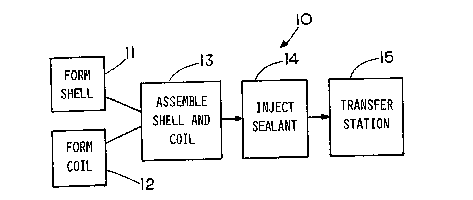
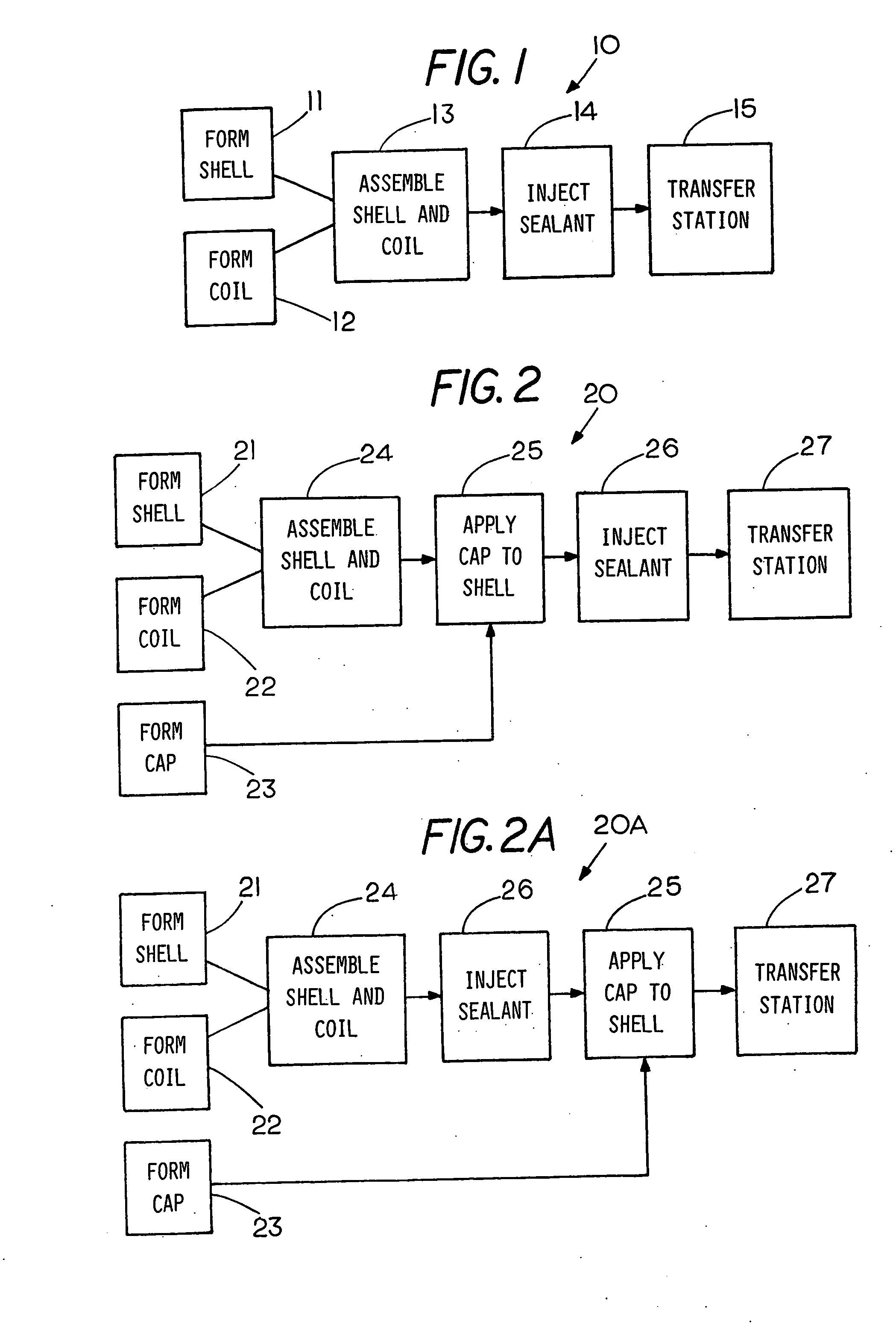
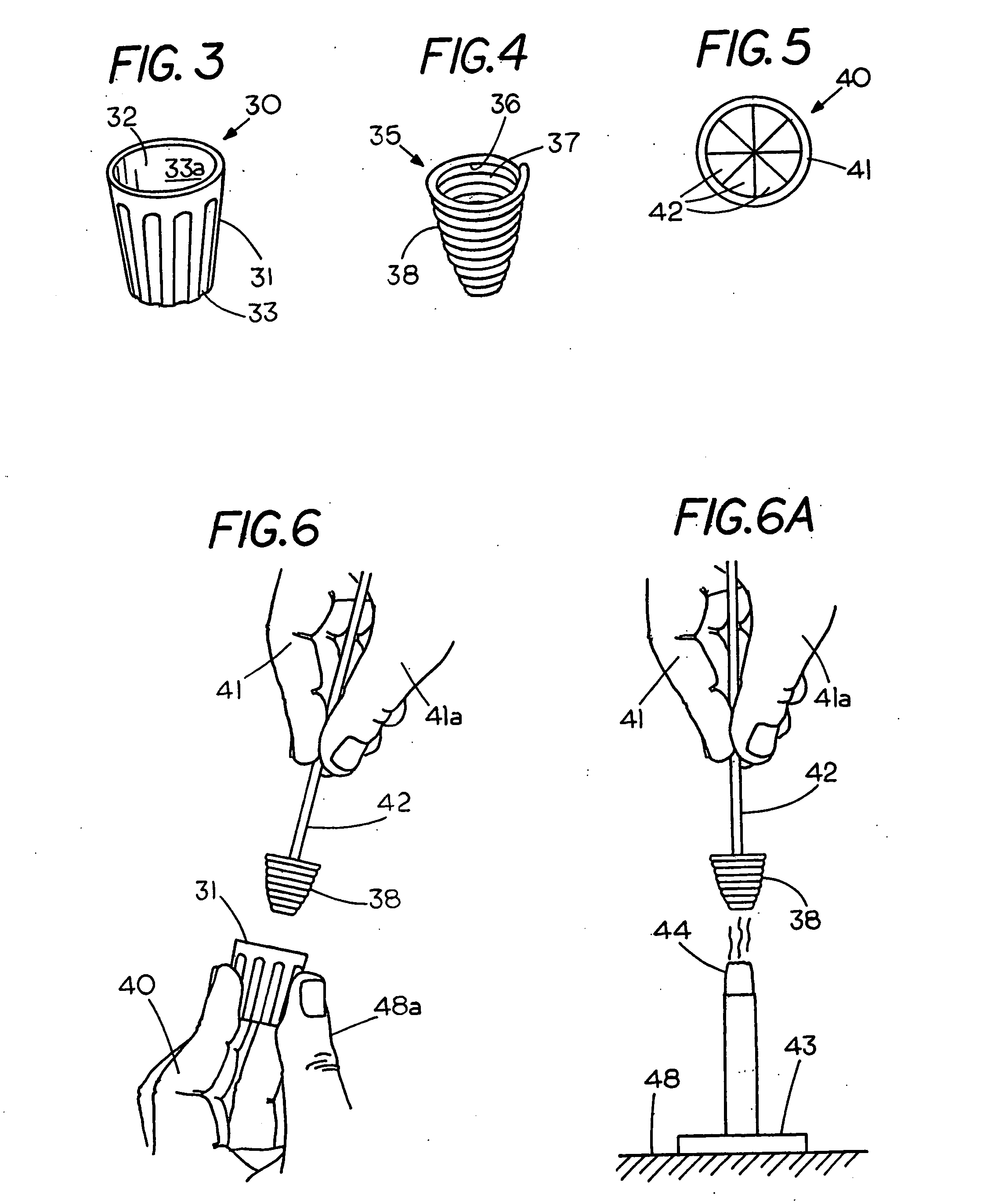
[0026]FIG. 1 shows a block diagram of a system 10 for generating a sealant containing twist-on wire connector. System 10 includes a station 11 wherein a component such as hard shell for a twist-on wire connector is formed. Typically, the hard shell can be formed by molding although other methods of forming the hard shell may be used. An example of a hard shell 30 is illustrated in FIG. 3 and comprises a cylindrical tube like member 31 with a closed end 33 and an open end 32 forming an interior pocket 33a therein. Example of hard shells for twist-on wire connecters can be found in U.S. Pat. No. 5,023,402. A further component is a coil 35, which is shown in FIG. 4, with the coil having a spiral shape with an inner cavity 37 and an outer surface 38 for engaging the interior of wire connector shell 30 and a wire engaging surface 36 for engaging wires to hold the wires in a cavity 37 located in coil 35.

[0027]FIG. 5 shows a top view of a further component of a twist-on wire connector that...


PUM


Abstract

An improved method of making sealant containing twist-on wire connectors from a batch of components, wherein some of the components may be preassembled through automated equipment and at least one or more of the steps performed in the making of a sealant containing twist-on wire connector is performed manually at a station where an operator can simultaneously perform one or more steps to enhance the formation of a twist-on wire connector containing a sealant while at the same time eliminating upfront investments costs for a work station as well as costs for maintenance of a work station.

Description

FIELD OF THE INVENTION[0001]This invention relates generally to twist-on wire connectors and, more specifically, to improvements to a process of making sealant containing twist-on wire connectors.CROSS REFERENCE TO RELATED APPLICATIONS[0002]NoneSTATEMENT REGARDING FEDERALLY SPONSORED RESEARCH OR DEVELOPMENT[0003]NoneREFERENCE TO A MICROFICHE APPENDIX[0004]NoneBACKGROUND OF THE INVENTION[0005]Twist-on wire connectors are well known in the art and generally comprise a hard shell with a spiral wire core located in a cavity in the shell. The ends of wires, which are to be connected together, are inserted into contact with the spiral wire core and the wires and twist-on wire connector are rotated with respect to each other to bring the electrical wires into electrical contact with each other. Typically, such wire connectors are assembled on automated machines that form the coil and the hard shell and automatically insert the the coil into the hard shell.[0006]A modified twist-on wire con...

Claims


Application Information

Patent Timeline
IPC IPC(8): H01R43/18H01R4/00H01R4/22
CPCH01R4/22H01R43/00Y10T29/49224Y10T29/49004Y10T29/5137Y10T29/49201Y10T29/49208Y10T29/49211H01R43/24
Inventor KING, JR., LLYOD HERBERTKEEVEN, JAMES C.
Owner THE PATENT STORE
Why Eureka
Try Eureka