Electrical apparatus with a contacting device

Inactive Publication Date: 2009-12-24
ROBERT BOSCH GMBH
View PDF2 Cites 0 Cited by
  • Summary
  • Abstract
  • Description
  • Claims
  • Application Information

AI Technical Summary

Benefits of technology

[0009]Such a form of an electrical apparatus according to the present invention enables contact to be made with a component of the electrical apparatus in a simple and cost-effective manner, with no great forces being exerted in the longitudinal direction of the contacting device and thermal warming being prevented, which minimizes rejects when producing such electrical devices.
[0020]In order to be able to support joining forces that occur using auxiliary geometries, it is advantageous if the housing part partially encloses the electrical component, and preferably has a cutout on a side opposite the electrical component to achieve tolerance compensation. Furthermore, the contacting area is then enclosed particularly effectively by the housing part, which increases the protection against fouling still further.

Problems solved by technology

The electrical apparatus thus remains fail-safe even in long-term use.

Method used


Image

  • Electrical apparatus with a contacting device
  • Electrical apparatus with a contacting device
  • Electrical apparatus with a contacting device

Examples


Embodiment Construction

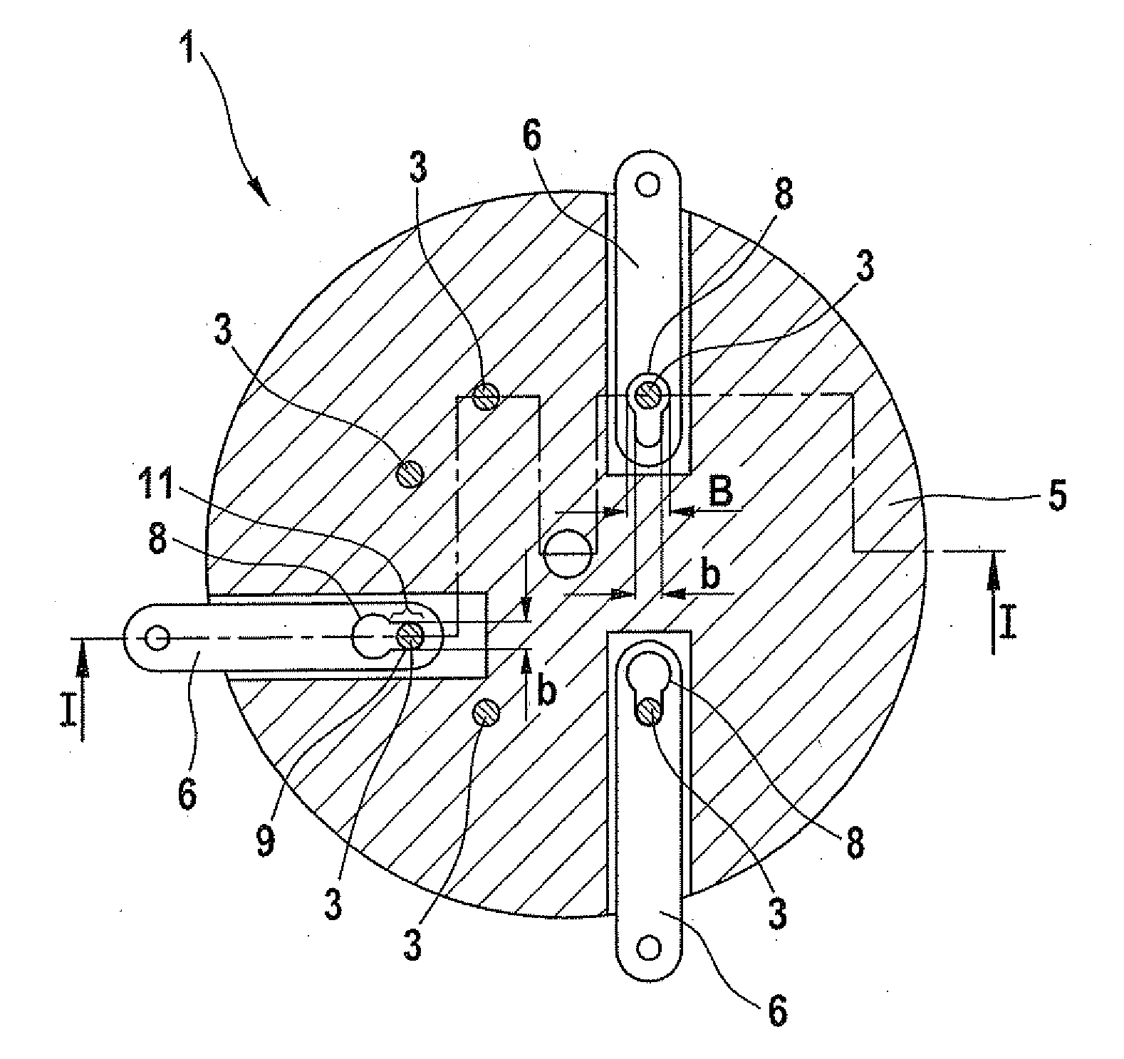
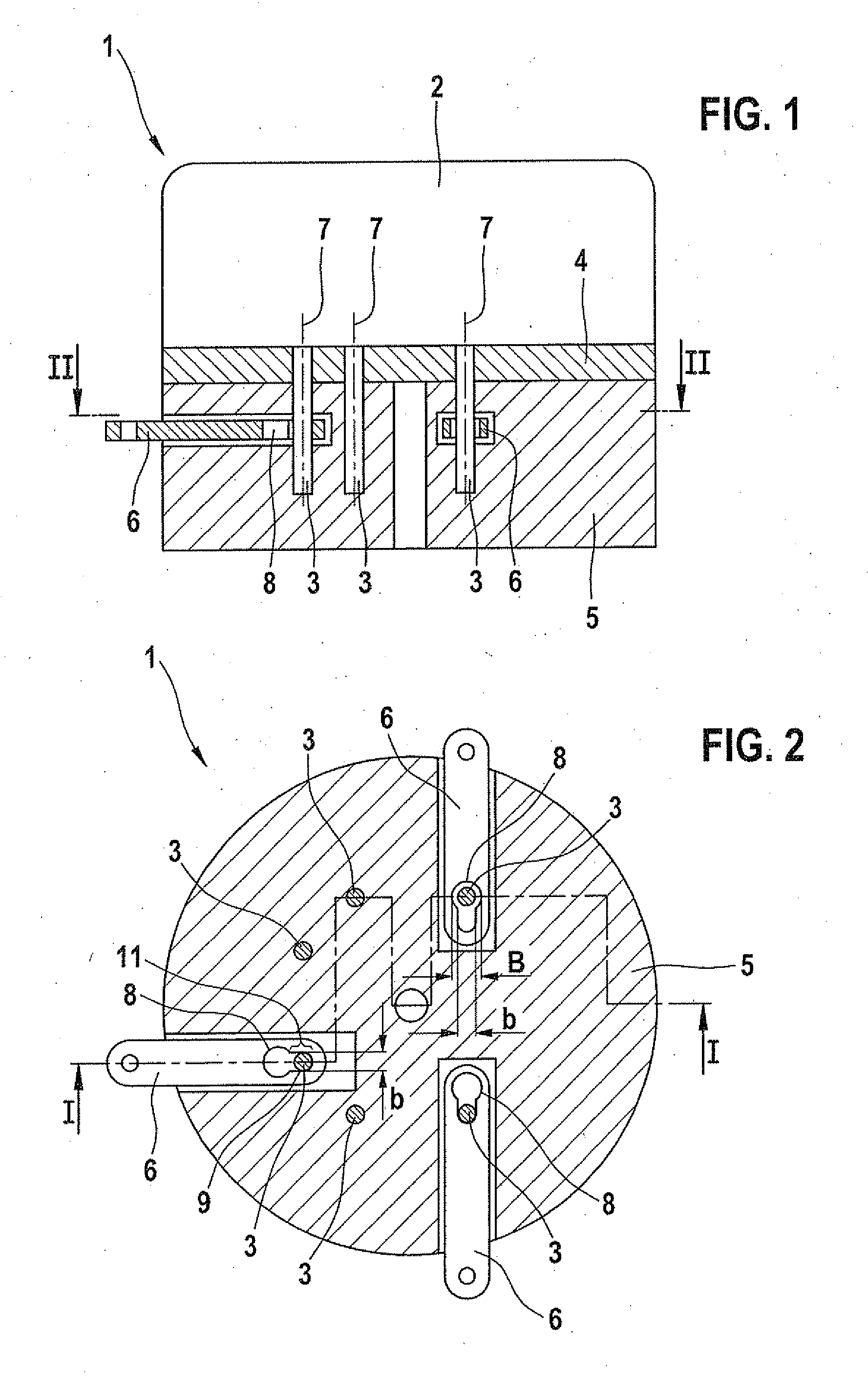
[0025]FIG. 1 shows an electrical apparatus according to the present invention in a staggered cross section. The shape of the staggered cross section may be seen in FIG. 2, where it is provided with reference numeral I.

[0026]Electrical device 1 has an electrical component 2 on its top which is a sensor or control unit, in particular a pressure sensor. Electrical component 2 has at least one contacting device 3. Contacting device 3 is either a pin, a wire, a braided strand, or a similar component.

[0027]In the lower zone of electrical component 2 a fixing material 4 is applied, which is made in particular of glass or epoxy resin and which fixes at least one contacting device 3. Fixing material 4 encloses at least part of contacting device 3, and does not have to cover the entire cross-sectional area of electrical component 2 as shown.

[0028]The connection of contacting device 3 with circuit elements in electrical component 2 is not shown. Conventional approaches for this are adequately ...


PUM


Abstract

An electrical apparatus, in particular a sensor or a control unit, includes at least one component that has at least one contacting device such as a pin or a wire, where the contacting device engages a clamping section of a housing part to produce an electrical connection and has a longitudinal axis, the clamping section being formed as part of a sliding device that is situated in the housing part and is movable transversely to the longitudinal axis of the contacting device.

Description

FIELD OF THE INVENTION [0001]The present invention relates to an electrical apparatus, in particular a sensor or a control unit, having at least one component that has at least one contacting device such as a pin or a wire, where the contacting device engages a clamping section of a housing part to produce an electrical connection and has a longitudinal axis.BACKGROUND INFORMATION [0002]The use of cut-and-clamp and clamping techniques is known from the related art, such as cut-and-clamp connections, which are also known as ID connections, for insulation displacement. Such insulation displacement connections are solderless, permanent electrical connections which are produced by pressing a conductor into a tapered slot in a terminal. Such a conductor is either a single wire, is made up of a plurality of wire strands, or is a solid metal pin.[0003]When the conductor is inserted into the slot the flanks of the slot displace any insulation that is present, deform the conductor, and thus ...

Claims


Application Information

Patent Timeline
IPC IPC(8): H01R4/24
CPCG01D11/245G01D11/30H01R43/16H01R4/26H01R4/2416
Inventor ZWEIGLE, PETERARENS, CHRISTIAN
Owner ROBERT BOSCH GMBH
Why Eureka
Try Eureka