Integral Personal Watercraft Shaft Sealing Axial Alignment Systems

US20210371077A1Active Publication Date: 2021-12-02WATHEY CHAD
3 Cites 0 Cited by

Patent Information

Authority / Receiving Office
US · United States
Current Assignee / Owner
Publication Date
2021-12-02

Smart Images

  • Figure 1
    Figure 1
  • Figure 2
    Figure 2
  • Figure 3
    Figure 3
Patent Text Reader

Abstract

A clamping mechanism is provided. The mechanism includes a male clamping body. The mechanism also includes a female clamping body configured to mate with the male clamping body. The mechanism further includes tightening bolts structured to connect the male clamping body to the female clamping body. The mechanism includes connecting spans connected to the male clamping body and the female clamping body. The mechanism also includes integral positioning ring halves connected to the male clamping body and the female clamping body, wherein the positioning rings are designed to fit into a positioning groove of a drive shaft and to provide a backstop to a support ring. Also, the connecting spans, the male clamping body, and the female clamping body have inner diameters that are identical and are arranged to securely fit onto an outer surface of the drive shaft when the tightening bolts are tightened.
Need to check novelty before this filing date? Find Prior Art

Description

FIELD OF THE INVENTION

[0001] The present invention relates generally to shaft sealing systems, and more particularly, to integral personal watercraft shaft sealing axial alignment systems which provide the ability to secure the components of a shaft sealing system with redundancy.BACKGROUND OF THE INVENTION

[0002] Many methods and systems have been used in unsuccessful attempts to provide mechanisms to provide an efficient, effective, and inexpensive way to provide redundancy to shaft sealing components. These systems and methods have not been reliable or effective. Many of the unsuccessful systems are cumbersome, costly and fail to provide all of the necessary material and physical features on a singular platform.

[0003] Current attempts include utilization of a single loose approximately 180 degree C-clip with a curvature radius slightly smaller than the radius of the drive shaft groove. The drive shaft has a predetermined groove to align axially where the drive shaft support ring is t...

Examples

Embodiment Construction

[0030]The present invention will now be described more fully hereinafter with reference to the accompanying drawings, in which preferred embodiments of the invention are shown. This invention may, however, be embodied in many different forms and should not be construed as limited to the embodiments set forth herein. Rather, these embodiments are provided so that this disclosure will be thorough and complete, and will fully convey the scope of the invention to those skilled in the art.

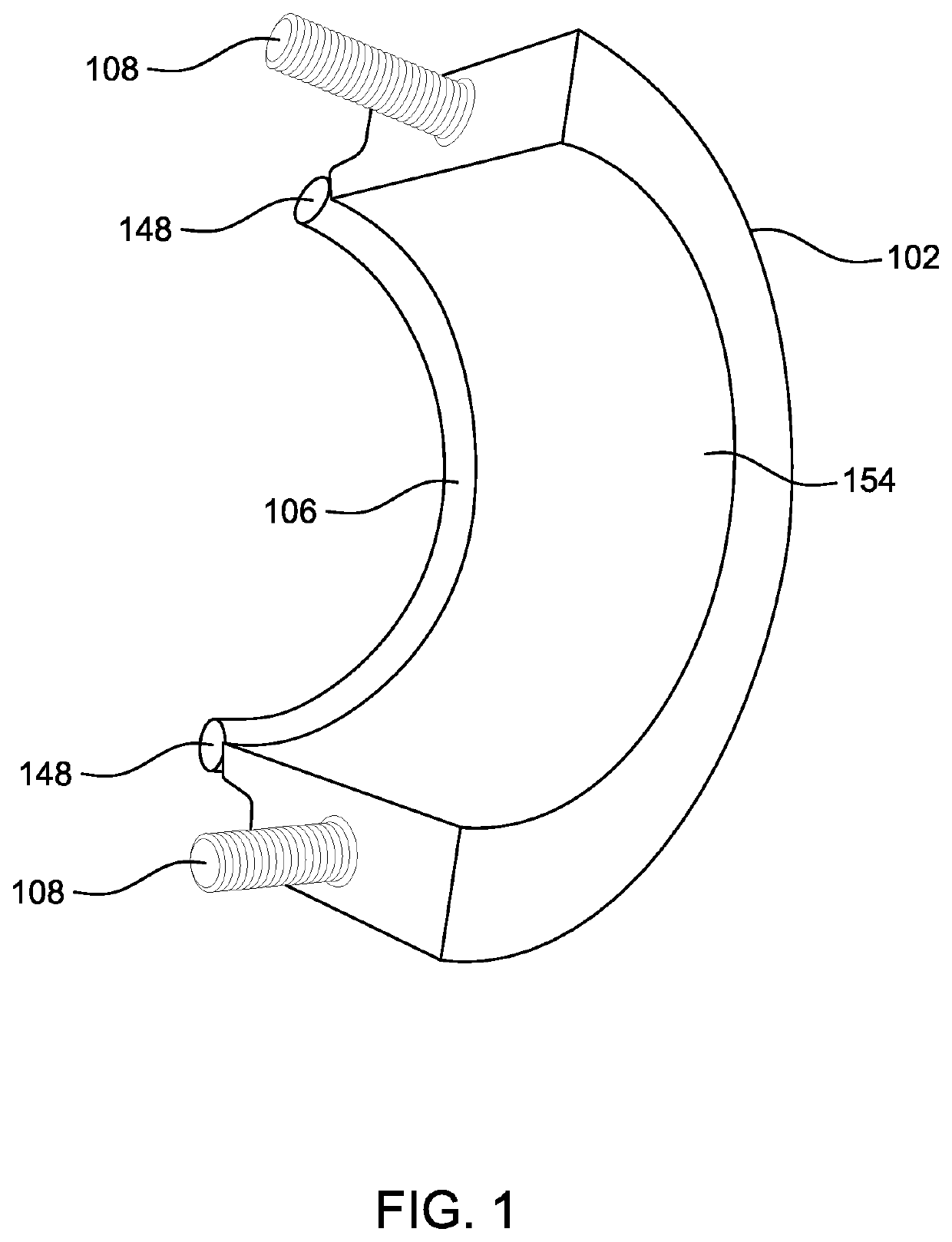
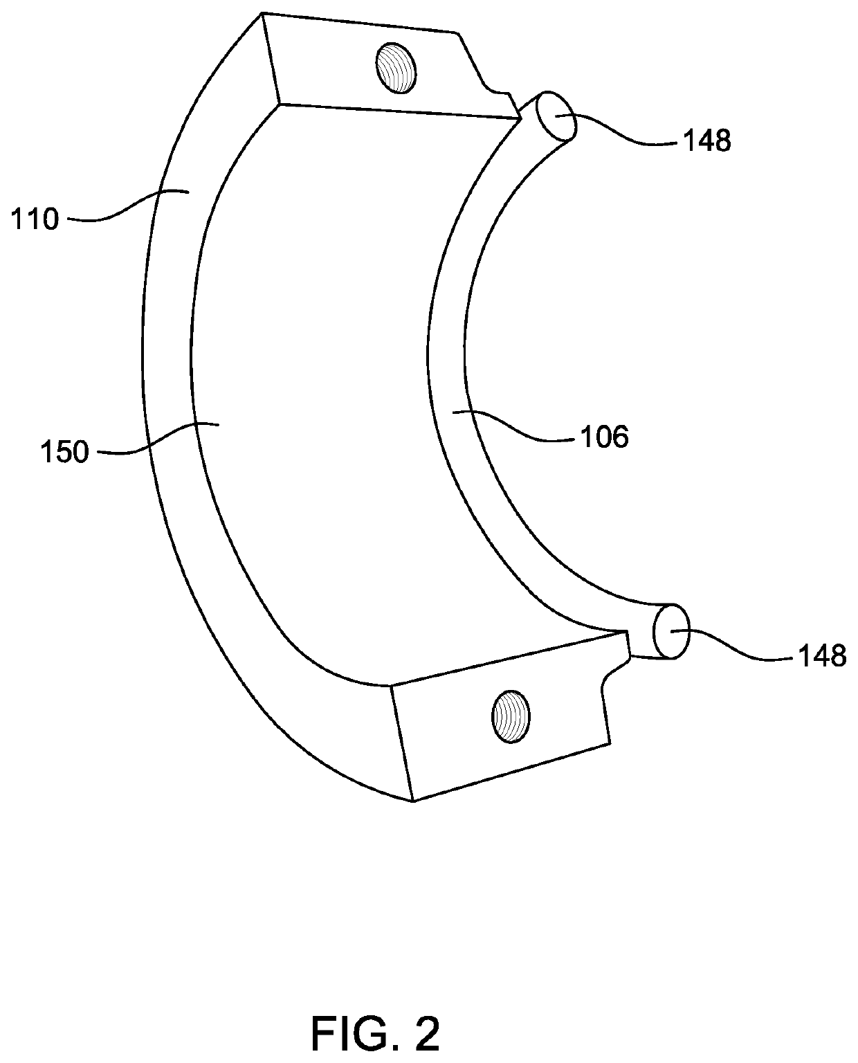
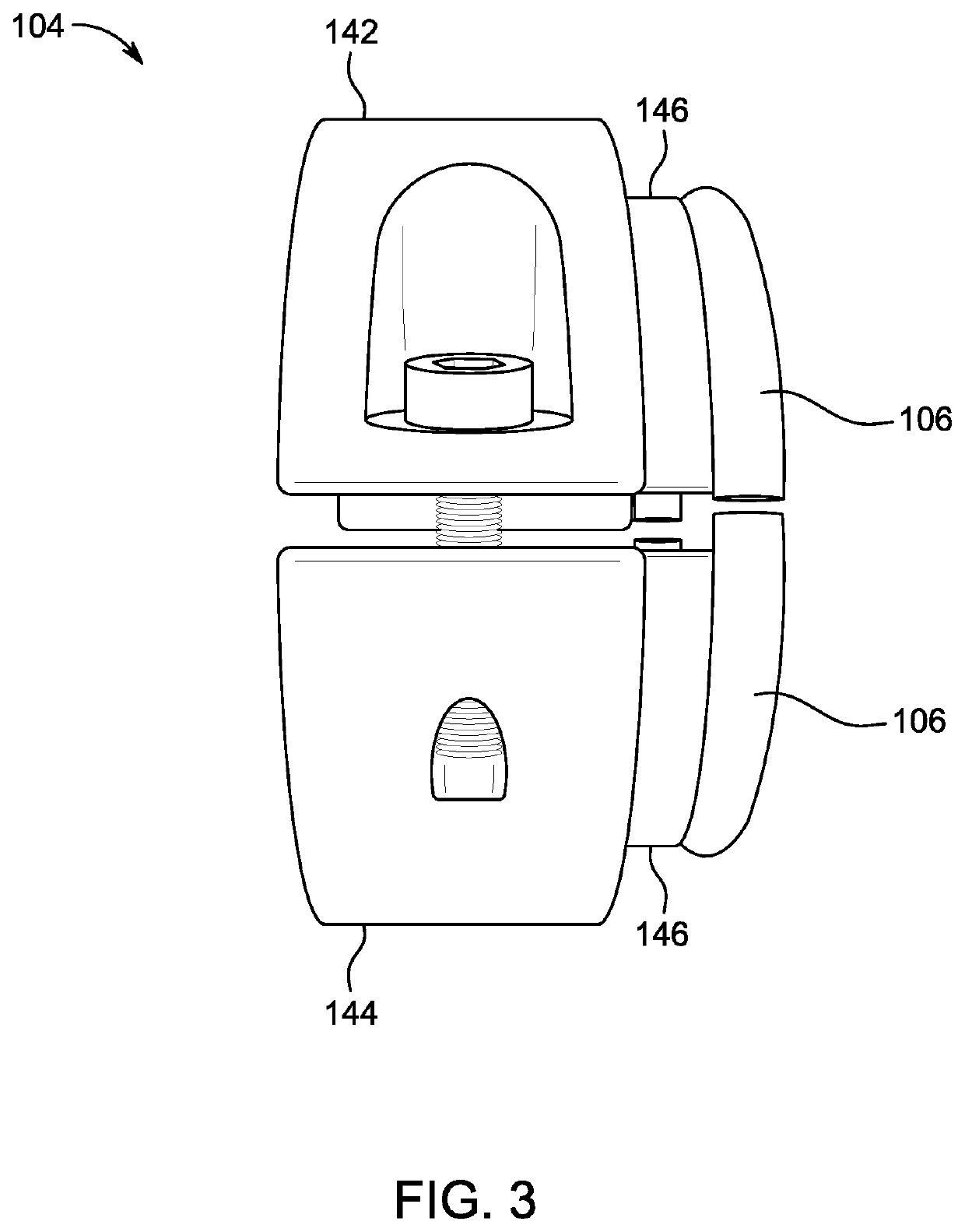
[0031]FIG. 1 shows an internal view of an embodiment of a clamping mechanism 104. The mechanism 104 includes a male portion 102 of the clamping mechanism 104. The clamping mechanism includes an integral positioning ring 106. The clamping mechanism 104 also includes fastening bolts 108 to attach the male portion 102 of the clamping mechanism 104 to a female portion 110. As seen in FIG. 1, the male portion 102 of the clamping mechanism 104 includes an interior surface 154 designed to grip onto the externa...