
Method and device for discharging coarse granule slurry in decomposition production process of aluminum oxide

A production process, alumina technology, applied in the direction of alumina/aluminum hydroxide, etc., can solve the problems of reduced production capacity, failure to meet production needs, and increased production costs, so as to prevent overload operation, improve product quality, and factory production capacity Improved effect

Inactive Publication Date: 2014-05-07
GUIYANG AL-MG DESIGN & RES INST
View PDF7 Cites 0 Cited by
  • Summary
  • Abstract
  • Description
  • Claims
  • Application Information

AI Technical Summary

Problems solved by technology

These coarse grains and scabs deposit to the bottom of the decomposition tank. When deposited to a certain extent, the product quality will be seriously affected, and the decomposition stirring motor of the decomposition tank agitator will be overloaded, resulting in failure or damage.
In order to avoid the occurrence of these failures and shorten the operation period of the decomposition tank, the method of increasing the number of shutdowns for cleaning is generally used in the prior art to discharge the coarse particle slurry in the decomposition tank during the alumina decomposition production process. The existing method Not only will it lead to a reduction in the utilization rate of the equipment (reducing the production capacity of the plant), but it will also increase the cleaning workload, increase labor intensity, increase production costs, and increase the coarse particle content of the product, resulting in low product quality. drop
Therefore, the existing method of discharging coarse particle slurry during the production process of alumina decomposition is not ideal and cannot meet the needs of production

Method used


Image

  • Method and device for discharging coarse granule slurry in decomposition production process of aluminum oxide

Examples


Embodiment Construction

[0015] The present invention will be further described in detail below in conjunction with the accompanying drawings and embodiments.

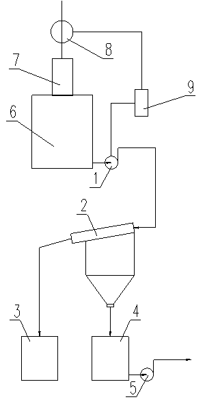
[0016] Embodiment of the present invention: a schematic diagram of the structure of a device for discharging coarse particle slurry during the production process of alumina decomposition of the present invention is as follows figure 1 As shown, the device includes the existing alumina decomposition tank 6. During manufacture, the upper row coarse slurry pump 1 is installed on each alumina decomposition tank 6, and the feed port of the row coarse slurry pump 1 is set At the bottom of the alumina decomposition tank 6, the outlet end of the coarse slurry pump 1 is connected to the upper row of coarse screen 2 through a pipeline, and the row of coarse screen 2 can adopt an existing screen with a sieve diameter less than or equal to 150 μm Finished product; Then a coarse particle slag collection box 3 is set at the coarse material discharge port of...


PUM


Abstract

The invention discloses a method and a device for discharging coarse granule slurry in the decomposition production process of aluminum oxide. The method comprises the following steps of: assembling a coarse slurry discharge pump on each aluminum oxide decomposition groove; discharging coarse granule slurry at the bottom of the aluminum oxide decomposition groove by using the coarse slurry discharge pump; filtering the coarse granule slurry discharged by the coarse slurry discharge pump by using a coarse granule slurry discharge sieve; separating out coarse granule slag and fine granule slurry; conveying and returning the fine granule slurry by using the slurry pump to the aluminum oxide decomposition groove of a decomposition system; and exporting the coarse granule slag for sale or returning the coarse granule slag to the aluminum oxide production system, wherein the coarse granule slag serves as production raw materials. The device has the advantages of simple structure, high working efficiency, convenience and easiness in operation and capacity of improving product quality and also has the advantages of greatly reducing labor intensity of workers, contributing to environment friendliness, reducing production cost, saving raw materials, reducing energy consumption and the like.

Description

technical field [0001] The invention relates to a method and a device for discharging coarse particle slurry during the production process of alumina decomposition, and belongs to the technical field of alumina decomposition process equipment. Background technique [0002] At present, the decomposition in the existing alumina production mostly adopts multiple large-scale mechanical stirring decomposition tanks (each tank is 2500-6000M 3 ) in series to form a series of continuous decomposition processes, and have strict requirements on the particle size of the product slurry, in which the particle size of 150 μm is not greater than 3.0%. However, coarser particles and scabs are unavoidable in the decomposition production process; especially the harder scabs attached to the inner wall of the decomposition tank and the agitator of the decomposition tank, in the form of coarser particles or even lumps or flakes The formation of the shape falls off and enters the slurry in the d...

Claims


Application Information

Patent Timeline
Patent Type & Authority Patents(China)
IPC IPC(8): C01F7/02
Inventor 高振文白英伟
Owner GUIYANG AL-MG DESIGN & RES INST
Learn More