Sliding wheel component and numerical control machine tool pull hood adopting sliding wheel component

A pulley assembly, CNC machine tool technology, used in maintenance and safety accessories, metal processing mechanical parts, metal processing equipment, etc., can solve the problem of the tool rest not working normally, detaching from the guide rail, etc., to ensure the processing efficiency and ability, and smooth operation. , the effect of not easily deformed

CN108356597APending Publication Date: 2018-08-03SHANXI PINGYANG IND MACHINERY
0 Cites 0 Cited by

Patent Information

Authority / Receiving Office
CN · China
Patent Type
Applications(China)
Current Assignee / Owner
Publication Date
2018-08-03

Smart Images

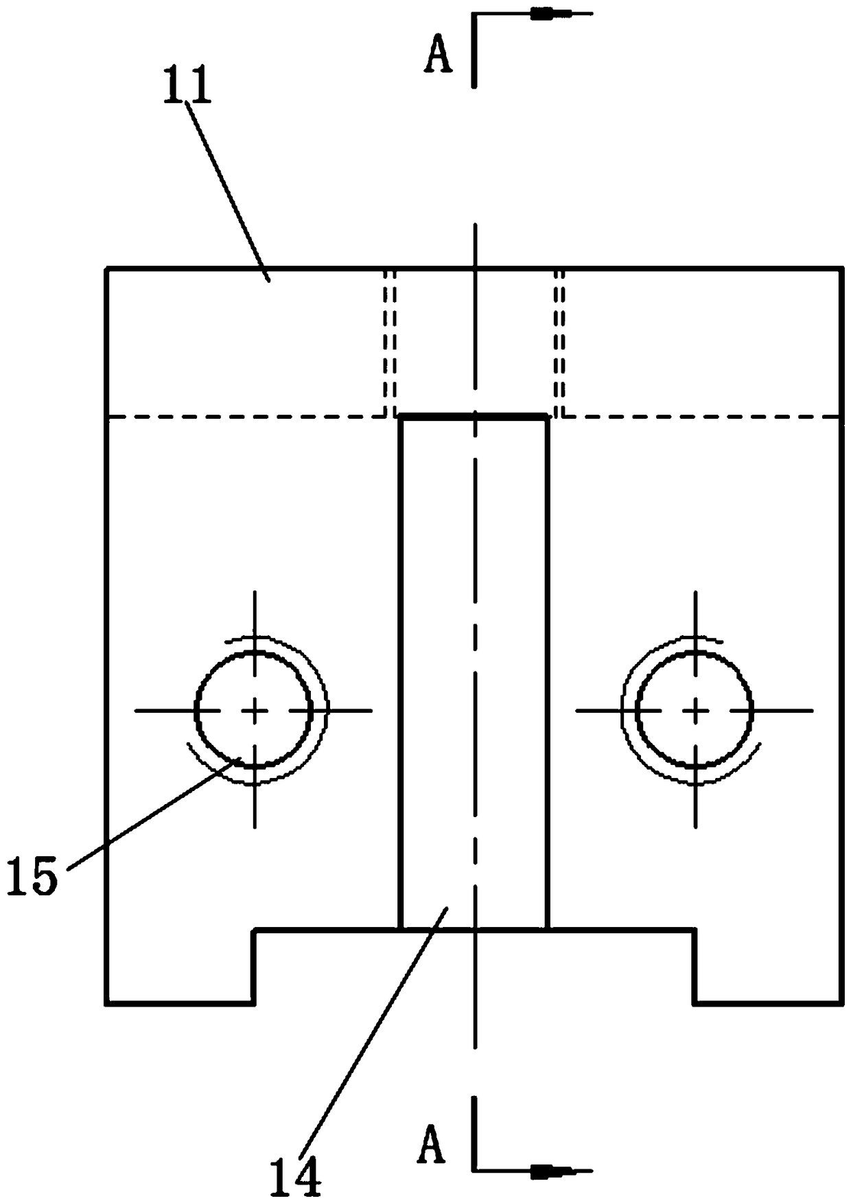
  • Figure 1
    Figure 1
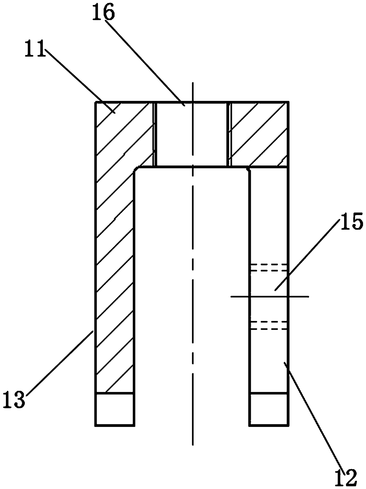
  • Figure 2
    Figure 2
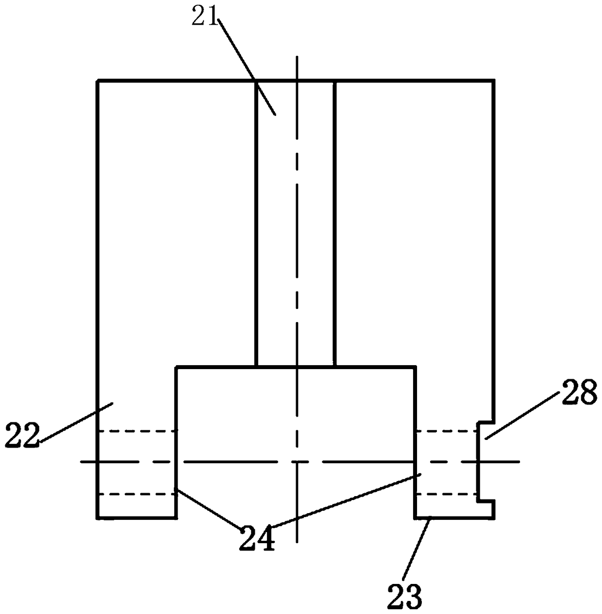
  • Figure 3
    Figure 3
Patent Text Reader

Abstract

The invention relates to the installation technology of numerical control machine tool pull hoods and machine tools, in particular to a sliding wheel component and the numerical control machine tool pull hood adopting the sliding wheel component. By means of the sliding wheel component and the numerical control machine tool pull hood adopting the sliding wheel component, the problem that sliding wheels for the current numerical control machine tool pull hoods break away from guide rails to make a cutter platform can not work normally is solved. The sliding wheel component comprises a fixed block and a sliding block, the sliding block is inserted into a long slot formed between the front extended segment and the rear extended segment of the fixed block, a vertical embossment is located inside a position-limiting vertical slot, screw holes are each internally distributed and provided with a fastening bolt used for fixing the sliding block correspondingly, a pin shaft hole running throughthe left extended segment and the right extended segment is provided with a pin shaft, the end, located on the outer side of one of the extended segments, of the pin shaft is provided with compressing nuts in a sleeved manner, the part, located between the left extended segment and the right extended segment, of the pin shaft is rotatably provided with an idler wheel in a sleeved manner, and a threaded hole penetrating through the center of a base seat is provided with a jackscrew used for adjusting the height of the sliding block. The sliding wheel component and the numerical control machinetool pull hood adopting the sliding wheel component are provided with a sliding block structure, up and down positions of the sliding wheels can be conveniently adjusted, each sliding wheel set can touch the guide rail, and the whole pull hood runs smoothly.
Need to check novelty before this filing date? Find Prior Art

Description

technical field

[0001] The invention relates to a numerical control machine tool pull cover and the installation technology of the machine tool, in particular to a pulley assembly and a numerical control machine tool pull cover using the pulley block. Background technique

[0002] In recent years, as the processing capacity of the national machinery and equipment manufacturing industry has been greatly improved, and people's requirements for the environment, processing quality, processing efficiency, personal safety and health have become higher and higher, CNC machine tools have undoubtedly become the first choice of most manufacturers. Processing Equipment. Combined with our company's CNC machine tools, there are four pull covers on each CNC car, and the two pairs are stretched and matched with each other through seals. Driven by the tool table of the machine tool, they run smoothly on the guide rails to block cutting fluid and iron filings. .

[0003] The newly-purchase...

Examples

Embodiment Construction

[0042] A pulley assembly, including a fixed block 1 and a slider 2; the fixed block 1 includes a rectangular base 11, and the front and rear parts of the bottom of the base 11 respectively extend downwards against the front and rear sides of the bottom to form front and rear extensions 12, 13; where the middle of the front extension section 12 is downwardly opened with a limit vertical groove 14 which divides the front extension section 12 into left and right parts by the bottom surface of the base 11; Through screw holes 15; the center of the base 11 has a threaded hole 16 through up and down; the slider 2 comprises a cuboid structure, and the middle part of the front side of the cuboid structure is provided with a vertical protrusion matched with the limit vertical groove 14. 21, the slide block 2 is inserted into the long groove formed between the front and rear extension sections 12, 13 of the fixed block and the vertical protrusion 21 is located in the limit vertical groov...