Double Hammer Clutch Impact Wrench

a double hammer clutch and impact wrench technology, which is applied in the direction of wrenches, power driven tools, screwdrivers, etc., can solve the problems of unnecessarily pushing the hammer, unable to produce any additional torque, and completely miss the anvil, so as to increase the torque and increase the torque

Inactive Publication Date: 2010-03-18
S P AIR
View PDF22 Cites 20 Cited by
  • Summary
  • Abstract
  • Description
  • Claims
  • Application Information

AI Technical Summary

Benefits of technology

[0009]In another aspect of the invention, the tool comprises a housing with first and second ends and a longitudinal axis extending between the ends. A head is attached to the housing toward the first end for operatively engaging the mechanical fastener. A motor with a motor shaft is disposed in the housing toward the send end for driving the head. An impact drive is disposed in the housing between the motor and the head and operatively connects the motor to the head. The impact drive has an input connected to a cam plate and a pair of pivotable hammers. The hammers are biased by the cam plate toward a striking position. The impact drive also has an output shaft disposed for rotation in response to rotation of the input. The hammers intermittently strike the output shaft for increasing the torque applied to the output shaft to selectively increase the torque transmitted to the head for tightening or loosening the mechanical fastener.
[0010]In yet another aspect of the invention, a pneumatic tool for tightening and loosening a mechanical comprises an elongate tubular housing sized for being held in one hand. A pneumatic motor in the housing has a motor shaft adapted to be rotated by the motor. An impact drive in the housing operatively connects to the motor shaft. The impact drive has an output shaft disposed for rotation and a pair of hammers pivotal bay a cam plate for intermittently providing an increased torque on the output shaft. The cam plate and the output shaft are generally coaxial. The impact drive is also fixed axially within the housing. A ratchet head assembly operatively connects to the output shaft of the impact drive. The ratchet head assembly includes an output member rotatably mounted on the hosing and capable of engaging the mechanical fastener. A ratchet mechanism is operable to limit rotation of the output member in one direction.

Problems solved by technology

This often occurs so rapidly that the hammers impact the anvils before corresponding surfaces fully register, or alternatively the hammers completely miss the anvils and fail to produce any additional torque.
Moreover, when the frictional resistance of the fastener exceeds the additional torque produced by the hammers, the cam ball and impact clutch may unnecessarily push the hammers into repeated registration with the anvils before an operator can disengage the motor.
This can be hard on components of the impact drive (e.g., the cam ball and impact clutch) and may damage them or prematurely wear them out before other components of the wrench.
While the components of the impact drive are less prone to damage and wear, the speed reducing mechanism requires the use of additional components which add complexity to the tool.

Method used


Image

  • Double Hammer Clutch Impact Wrench
  • Double Hammer Clutch Impact Wrench
  • Double Hammer Clutch Impact Wrench

Examples


Embodiment Construction

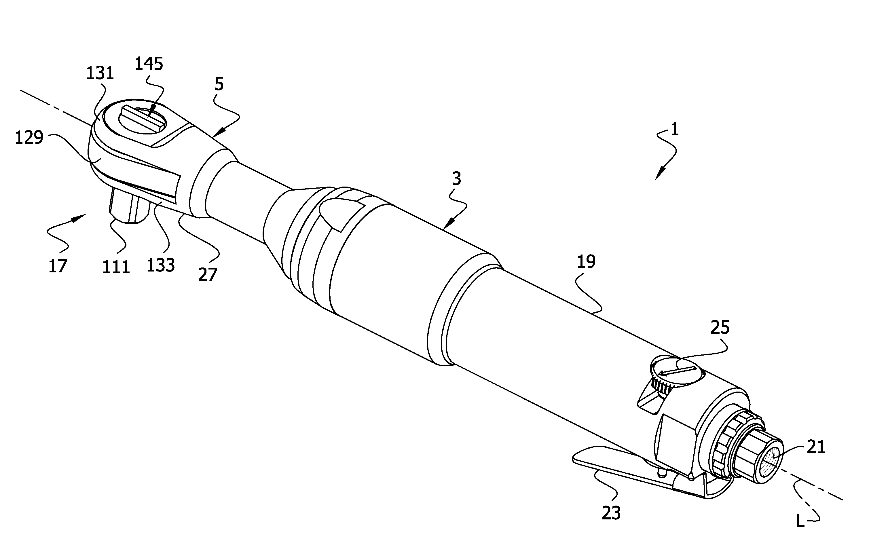
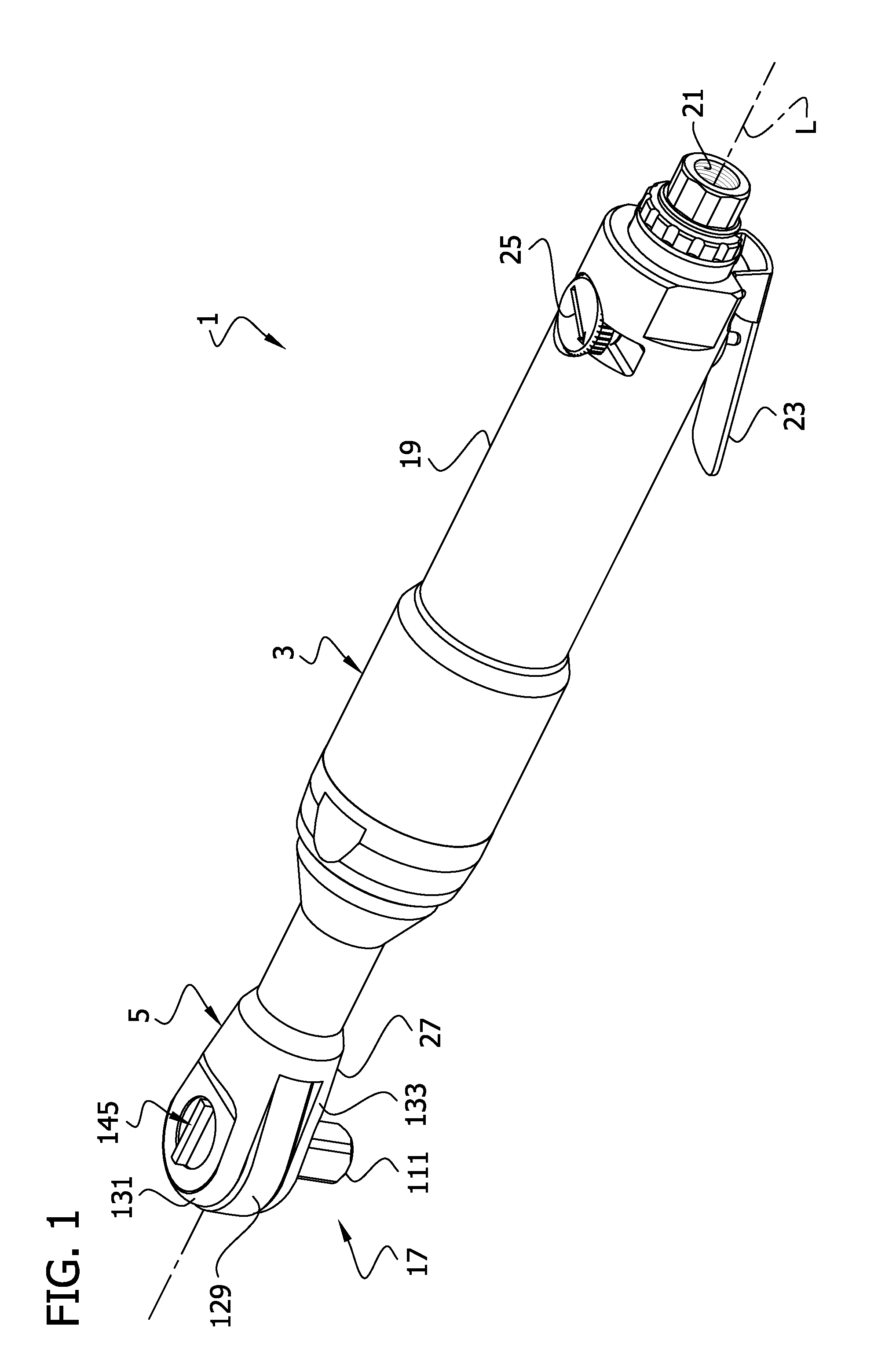
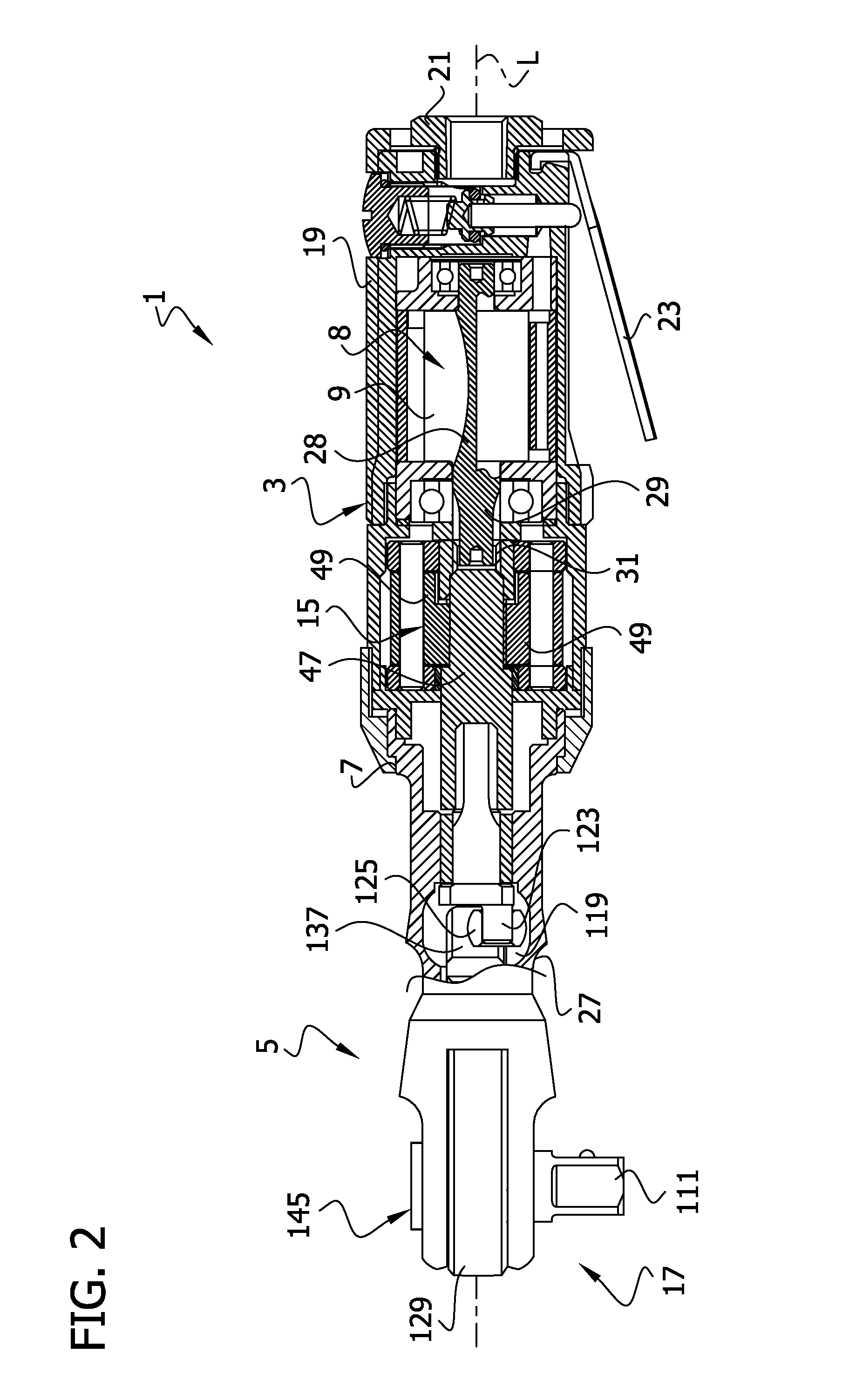
[0018]Referring now to the drawings, and particularly to FIGS. 1 and 2, a hand-held power driven ratchet wrench is generally indicated at reference numeral 1. The wrench 1 includes a tubular housing, indicated generally at 3, and a head, indicated generally at 5. As shown in FIG. 2, the housing 3 and head 5 are connected by a threaded internal coupling 7 and securely encase the functional components of the wrench 1, including a motor, generally indicated at 8, having a rotor 9. The housing 3 also contains an impact drive 15 and a ratchet mechanism 17 (the reference numerals designating their subjects generally). Each of these components will be described in greater detail hereinafter. For convenience of description, when describing orientation of these components, the head 5 is understood to be located toward a forward end of the wrench 1 and the motor 8 toward a rearward end. The motor 8 illustrated and described herein is a standard air driven motor of the type commonly used in pn...


PUM


Abstract

A power driven tool for rotating a mechanical fastener including a housing with a motor positioned in the housing. The motor includes a drive shaft that rotates relative to the housing. An impact mechanism in the housing is operatively connected to the motor drive shaft. The impact mechanism has a base, an output and a cam. The output and cam are rotatably mounted on the base. A pair of hammers are pivotally mounted on the base and selectively positioned by the cam. The cam biases the hammers to intermittently impact the output. A ratchet head assembly is operatively connected to the output of the impact mechanism. The ratchet head assembly includes an output member rotatably mounted on the housing to rotate the mechanical fastener. The assembly also includes a ratchet operable to limit rotation of the output member in a selected direction.

Description

CROSS-REFERENCE TO RELATED APPLICATIONS[0001]This application claims benefit of U.S. Provisional Patent Application No. 61 / 096,955, filed Sep. 15, 2008, and entitled, “Double Hammer Clutch Impact Wrench”, which is hereby incorporated by reference in its entirety.BACKGROUND OF THE INVENTION[0002]This invention relates generally to power driven tools, and more specifically it relates to a power driven tool for tightening or loosening fasteners having an impact drive with a double hammer clutch.[0003]Power driven tools for tightening or loosening fasteners (e.g., nuts and bolts) are known, and power driven tools incorporating impact drives that can intermittently provide an increased amount of torque for tightening or loosening fasteners are common.[0004]An impact wrench incorporating a ratchet head is disclosed in co-owned U.S. Pat. No. 4,821,611 (Izumisawa). A pneumatic motor rotates a clutch case that coaxially houses an impact drive. Under normal operation, a cam ball fixed within ...

Claims


Application Information

Patent Timeline
Patent Type & Authority Applications(United States)
IPC IPC(8): B25B19/00B25B13/46B25B21/00
CPCB25B21/004B25B21/02
Inventor KOBAYASHI, SHIGEKI
Owner S P AIR
Why Eureka
Try Eureka