Cool-storage type heat exchanger

a heat exchanger and cooling-storage technology, applied in indirect heat exchangers, lighting and heating apparatus, transportation and packaging, etc., can solve the problems of insufficient cooling down of cooling-storage devices, inability to efficiently cool down cooling-storage devices, and inability to etc., to achieve efficient cooling-energy and stably radiate stored cooling-energy.

Active Publication Date: 2010-03-18
DENSO CORP
View PDF14 Cites 55 Cited by
  • Summary
  • Abstract
  • Description
  • Claims
  • Application Information

AI Technical Summary

Benefits of technology

[0013]The present invention is made in view of the above problems. It is an object of the present invention to provide a cool-storage type heat exchanger, according to which it is capable of efficiently storing cooling-energy and stably radiating the stored cooling-energy.
[0014]It is a further object of the present invention to provide a cool-storage type heat exchanger, according to which a high productivity can be realized.

Problems solved by technology

Many proposals have been made, according to which a cooling operation is carried out, although it may be a limited operation, even when an operation of the refrigerating cycle is stopped.
Therefore, there is concern that the cooling-storage device may not be sufficiently cooled down.
When the air having high temperature comes in contact with the cooling-storage device, the stored cooling-energy is quickly carried away.
As above, it is difficult in the prior arts to efficiently cool down the cooling-storage device and to stably radiate the stored cooling-energy.
Therefore, it is difficult to obtain a high cooling capability.
Furthermore, since a cooling-storage material and a fin are arranged between neighboring refrigerant tubes, a high productivity may not be achieved.
According to such a structure, however, a high productivity may not be likewise achieved, because a plurality of cooling-storage cells is arranged between the refrigerant tubes.

Method used


Image

  • Cool-storage type heat exchanger
  • Cool-storage type heat exchanger
  • Cool-storage type heat exchanger

Examples


first embodiment

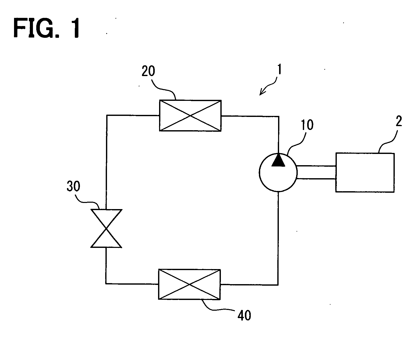
[0068]FIG. 1 is a schematic block diagram showing a refrigerating cycle 1 according to a first embodiment of the present invention. The refrigerating cycle 1 is used for an air conditioning apparatus for a vehicle. The refrigerating cycle 1 has a compressor 10, a heat radiating device 20, a depressurizing device 30, and a heat exchanger (an evaporator) 40. Those components are connected by refrigerant pipes in a closed circuit, so that refrigerant is circulated in the closed circuit. The compressor 10 is operated by a driving source 2, which is an internal combustion engine for driving the vehicle. Therefore, when the driving source 2 is stopped, the operation of the compressor 10 is also stopped. The compressor 10 draws the refrigerant from the evaporator 40, compresses the same and discharges the compressed refrigerant to the heat radiating device 20. The heat radiating device 20 cools down the high temperature refrigerant. The heat radiating device 20 is also referred to as a con...

second embodiment

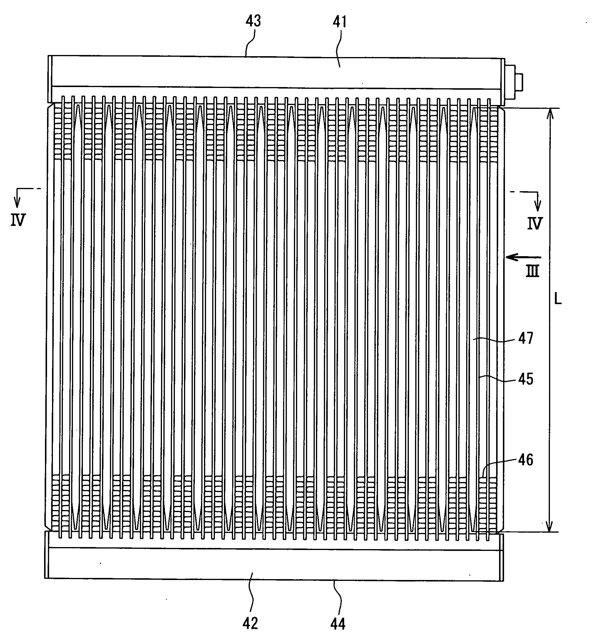
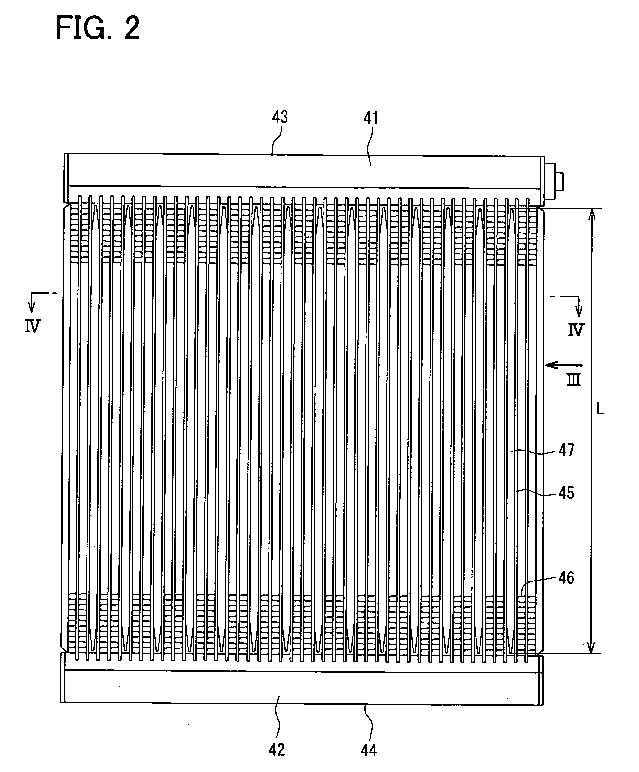
[0096]FIGS. 11 and 12 are enlarged partial views showing a heat exchanger (an evaporator) according to a second embodiment of the present invention, wherein FIG. 11 is a transverse sectional view and FIG. 12 is a longitudinal sectional view. FIG. 11 corresponds to a part of the cross sectional view taken along the line IV-IV of FIG. 2. FIG. 12 corresponds to a part of the cross sectional view taken along the line V-V of FIG. 3. The same reference numerals to the first embodiment are used for those portions in this embodiment, which are the same to the first embodiment.

[0097]A cooling-storage container 247 is formed as a flat tube having a rectangular cross-section. The cooling-storage container 247 has a pair of main wall portions 247a and a pair of side wall portions 247c. A corrugate type inner fin 247b forming a heat exchange portion is arranged inside of the cooling-storage container 247, wherein multiple top and bottom portions of the inner fin 247b are alternately arranged in ...

third embodiment

[0098]FIGS. 13 and 14 are enlarged partial views showing a heat exchanger (an evaporator) according to a third embodiment of the present invention, wherein FIG. 13 is a transverse sectional view and FIG. 14 is a longitudinal sectional view. FIG. 13 corresponds to a part of the cross sectional view taken along the line IV-IV of FIG. 2. FIG. 14 corresponds to a part of the cross sectional view taken along the line V-V of FIG. 3. The same reference numerals to the first embodiment are used for those portions in this embodiment, which are the same to the first embodiment.

[0099]A cooling-storage container 347 is formed as a flat tube having a rectangular cross-section, as in the same manner to the cooling-storage container 247 of the second embodiment (FIGS. 11 and 12). The cooling-storage container 347 has a pair of main wall portions 347a and a pair of side wall portions 347c. A corrugate type inner fin 347b forming a heat exchange portion is arranged inside of the cooling-storage cont...


PUM


Abstract

An object of the invention is to provide an effective cooling-energy storing performance and a stable cooling-energy radiating performance and to realize a high productivity. An evaporator has a plurality of refrigerant tubes arranged at almost equal intervals to form therebetween accommodating spaces. A plurality of cooling-storage containers are arranged in some of the accommodating spaces and fins are arranged in the remaining accommodating spaces. A cooling-storage unit is formed by one cooling-storage container and two refrigerant tubes arranged at both sides of the cooling-storage container. Each of the cooling-storage container has projections extending from one wall portion to the other wall portion to form heat exchange portions. The cooling-storage container is connected to the refrigerant tubes by soldering material.

Description

CROSS REFERENCE TO RELATED APPLICATION[0001]This application is based on Japanese Patent Applications No. 2008-235408 filed on Sep. 12, 2008 and No. 2009-77144 filed on Mar. 26, 2009, the disclosures of which are incorporated herein by reference.FIELD OF THE INVENTION[0002]The present invention relates to a cool-storage type heat exchanger to be used in a refrigerating cycle.BACKGROUND OF THE INVENTION[0003]A refrigerating-cycle is used for an air-conditioning apparatus. Many proposals have been made, according to which a cooling operation is carried out, although it may be a limited operation, even when an operation of the refrigerating cycle is stopped. For example, in case of the air-conditioning apparatus for a vehicle, the refrigerating cycle is operated by an engine for driving the vehicle. Therefore, when the engine operation is temporarily stopped during the vehicle is brought to a stop, the operation of the refrigerating cycle is likewise stopped. According to one of ideas,...

Claims


Application Information

Patent Timeline
Patent Type & Authority Applications(United States)
IPC IPC(8): F28D19/00F28F7/00
CPCF28D1/05383F28D20/00F28D20/02F28D2020/0013B60H1/005F28F2275/04Y02E60/142Y02E60/145F28D2021/0071Y02E60/14
Inventor YOKOYAMA, NAOKIMIYATA, YOSHIOHASEGAWA, ETSUOSHIMOYA, MASAHIROABEI, JUNSANADA, RYOICHIANDOH, TAKASHIINOUE, SEIJIENOMOTO, KATSUTOSHI
Owner DENSO CORP
Why Eureka
Try Eureka