Bi-directional horizontal spraying aerosol fire-extinguishing apparatus

a fire-extinguishing apparatus and bi-directional spraying technology, which is applied in fire rescue and other directions, can solve the problems of only referring to fire-extinguishing apparatus, no improvement in combustion speed, and low space-effectiveness, and achieve simple and safe way of installation and charging capacity. , the effect of reducing the effect of aging

Inactive Publication Date: 2010-03-18
SHAANXI J&R FIRE FIGHTING CO LTD
View PDF2 Cites 6 Cited by
  • Summary
  • Abstract
  • Description
  • Claims
  • Application Information

AI Technical Summary

Benefits of technology

[0011]The present bi-directional horizontal spraying aerosol fire-extinguishing apparatus can be installed on walls, ceilings or under anti-static electricity floors by mounting brackets. Furthermore, a cover with an exhaust perforated plate may be provided at both ends of the outer and inner cylinders respectively. And a flue tube may be provided on the outer surface of the cover for directing the aerosol smoke, thus ensuring spraying aerosol bi-directionally without occupying useful space. Therefore the arrangement makes it possible to install the apparatus in a simple and safe way.
[0012]Preferably, 4-10 blocking plates are provided in the cooling chamber located in the inner cylinder, ensuring that during the spraying of aerosol, the aerosol is sprayed smoothly without any coolant being carri

Problems solved by technology

Although the double-shell structure of the apparatus disclosed in ZL97248609.7 has some positive effect in reducing the temperature of the shell surface, it has the disadvantages of low space-effectiveness due to its huge and bulky body, and the designs described therein for heat-absorbing and fire-inhibiting are relatively simple.
The apparatuses disclosed in patent application 9912556.4 and patent ZL01277738.2 both have shutter-type sprayers and are respectively provided with baffle plates, fire-retardant and temperature regulating rods and meshworks, and retardant blocks, which have positive effect on aer

Method used


Image

  • Bi-directional horizontal spraying aerosol fire-extinguishing apparatus
  • Bi-directional horizontal spraying aerosol fire-extinguishing apparatus

Examples


Embodiment Construction

[0018]In the following description, the present invention will be further elucidated with reference to the appended drawings.

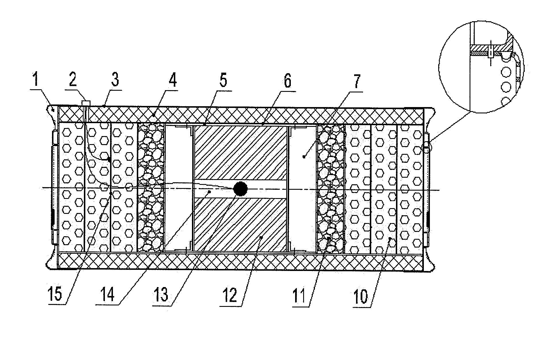
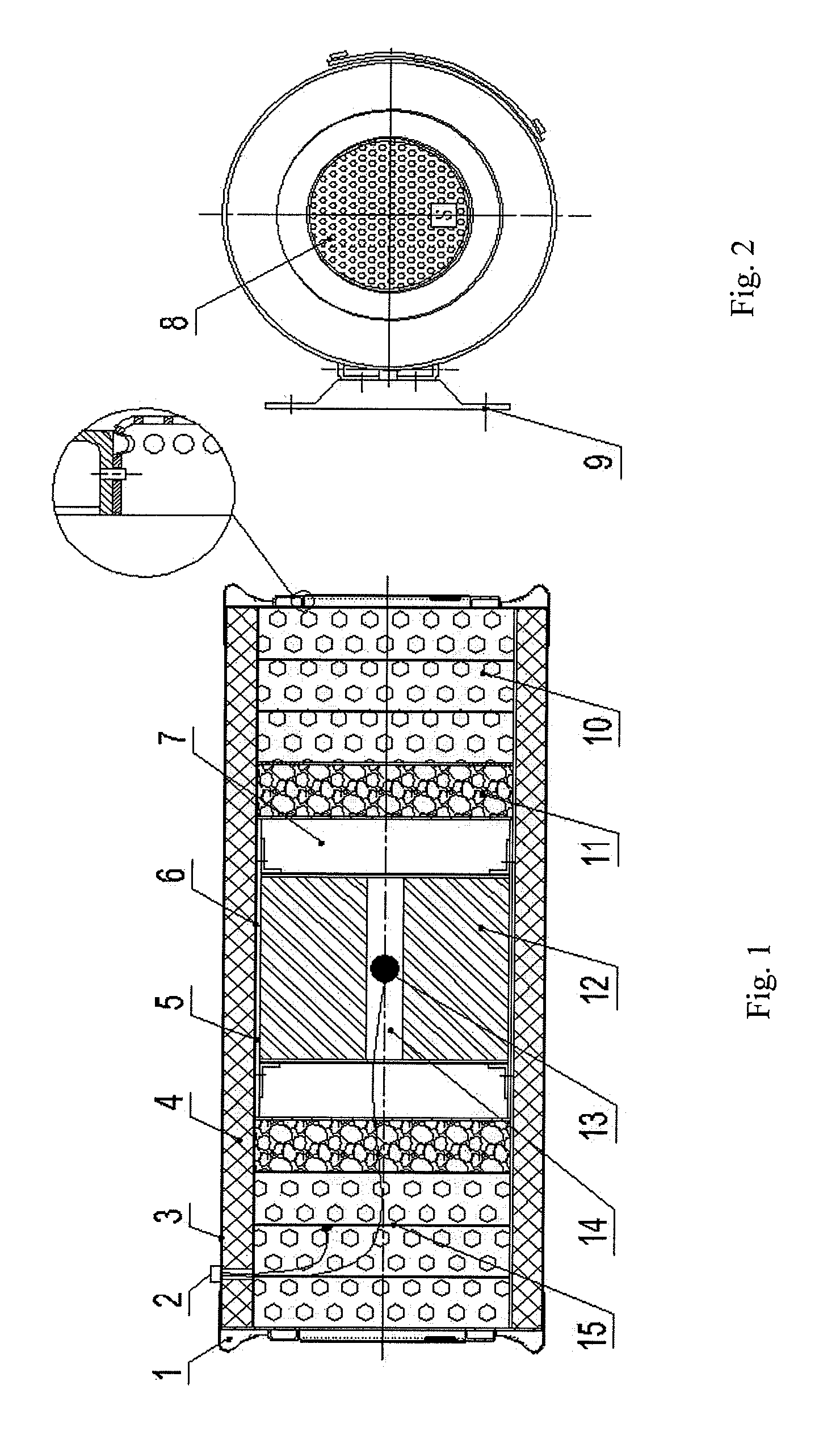
[0019]The present bi-directional horizontal spraying aerosol fire-extinguishing apparatus comprises an aerosol generator and an aerosol generating agent, an actuating device, a cooling device, a feedback unit and a shell structure. The feedback unit used herein refers to a control unit known by the skilled person in the art. As shown in FIG. 1, the said shell structure may be cylindrical, comprising an outer cylinder 3 and an inner cylinder 6. Thermal insulation material 4 is filled in the space between the outer cylinder 3 and the inner cylinder 6. Both ends of the outer cylinder 3 and the inner cylinder 6 are all as open exhaust passages and can be respectively provided with a cover 1 having an exhaust perforated plate 8 as shown in FIG. 2. The outer surface of the cover may be provided with a flue tube, such as a serpentine pipe. The said aerosol generator ...


PUM


Abstract

A new bi-directional horizontal spraying aerosol fire-extinguishing apparatus is disclosed, which comprises a shell structure, an aerosol generator including an aerosol generating agent and disposed inside the shell structure, and a control unit for initiating the aerosol generator. The bi-directional horizontal spraying aerosol fire-extinguishing apparatus of the present invention is characterized in that both ends of the shell structure or of the aerosol generator are respectively provided with an aerosol exhaust passage. The advantages of the present apparatus are in that it can reduce the spraying time of the aerosol extinguishing agent in the case of ensuring the fire-suppression efficiency, and increase the charge capacity of the fire-extinguishing apparatus, so that the capacity efficiency of the present apparatus is totally increased, and the present apparatus is easy and safe to be installed and does not occupy the useful space.

Description

TECHNICAL FIELD OF THE INVENTION[0001]This invention relates to a fire-extinguishing apparatus, specifically, a new bi-directional horizontal spraying aerosol fire-extinguishing apparatus.BACKGROUND OF THE INVENTION[0002]Since the enforcement of the “Montreal Protocol on Substances that Deplete the Ozone Layer”, which was signed in 1987 as the result of concerns of the international community on issues about ozone layer, Halon fire-extinguishing agent series, which account for more that ⅓ of the total amounts of ozone depleting chemicals used in fire-fighting industry, are gradually substituted by new kinds of fire-extinguishing products that are environment-friendly or relatively friendly. In recent years, the aerosol fire-extinguishing apparatus developed is a typical apparatus in the field of gas fire-extinguishing, this aerosol product is increasingly appreciated in fire-fighting industry and by research & development departments due to its advantages of no damage to ozone layer...

Claims


Application Information

Patent Timeline
IPC IPC(8): A62C31/00
CPCA62C5/006A62C99/0045A62C31/05
Inventor GUO, HONGBAOZHANG, ZANFENGZHANG, GUOXINGXIE, PENG
Owner SHAANXI J&R FIRE FIGHTING CO LTD
Why Eureka
Try Eureka