
Suspension arm having a shaft projecting therefrom and method for press fitting the shaft into a bore of another member

a technology of suspension arm and bore, which is applied in the direction of metal working apparatus, manufacturing tools, transportation and packaging, etc., can solve the problems of deformation of the suspension arm, and difficulty in holding the suspension arm in a stable manner, so as to achieve favorable support

Active Publication Date: 2010-03-18
HONDA MOTOR CO LTD
View PDF7 Cites 12 Cited by
  • Summary
  • Abstract
  • Description
  • Claims
  • Application Information

AI Technical Summary

Benefits of technology

[0006]In view of such problems of the prior art, a primary object of the present invention is to provide a suspension arm of a wheel suspension system that can be favorably supported when press fitting a shaft or pin projecting therefrom into a bore of another member.
[0007]A second object of the present invention is to provide a suspension arm that does not require a complex support base when press fitting a shaft or pin projecting therefrom into a bore of another member.
[0009]Because the opening allows the base end of the shaft to be supported, either directly or indirectly, against the force of the press fitting process, the remaining part of the suspension arm is not subjected to the force of the press fitting process. As the suspension arm is not required to be firmly clamped against the force of the press fitting process, the suspension arm is prevented from being deformed by the clamping force remaining part is not required. Also, as the suspension arm can be placed ready for the press fitting process simply by inserting an anvil into the opening, the work efficiency of the press fitting process can be improved as opposed to the case where a complex clamping fixture is used for the press fitting process.
[0010]Preferably, the opening allows direct access for an anvil to engage a base end surface of the base end of the shaft. No part of the suspension arm itself is thereby subjected to the force of the press fitting process, and the suspension arm can be supported in a both simple and stable manner.
[0012]According to a certain embodiment of the present invention, the opening is formed in each of the upper and lower plates in a mutually registered relationship such that an end surface of the shaft is recessed from corresponding edges of the openings, and the edges of the upper and lower plates may be supported by an anvil inserted into the opening. Because the reaction force of the anvil is applied to the base end of the shaft via a very short sections of the upper and lower plates, most part of the suspension arm is protected from the force of the press fitting process.
[0013]According to another embodiment of the present invention, the opening is defined by a recess formed in at least one of the upper and lower plates, and material of the at least one of the upper and lower plates is interposed between the recess and an end surface of the shaft. In this embodiment also, most part of the suspension arm is favorably protected from the force of the press fitting process.

Problems solved by technology

As the suspension arm has a complex shape, there is some difficulty in holding the suspension arm in a stable manner.
If the clamping force is excessively increased in an effort to firmly hold the suspension arm, the clamping force could deform the suspension arm.
Also, the force of the press fitting may also cause the deformation of the suspension arm depending on the way the suspension arm is held in position.
Such problems could be overcome by suitably designing the clamping arrangement, but increasing the complexity of the clamping arrangement is undesirable because it means in an increase in the cost of the assembling fixture, and a reduction in the work efficiency of the assembling process.

Method used


Image

  • Suspension arm having a shaft projecting therefrom and method for press fitting the shaft into a bore of another member
  • Suspension arm having a shaft projecting therefrom and method for press fitting the shaft into a bore of another member
  • Suspension arm having a shaft projecting therefrom and method for press fitting the shaft into a bore of another member

Examples


Embodiment Construction

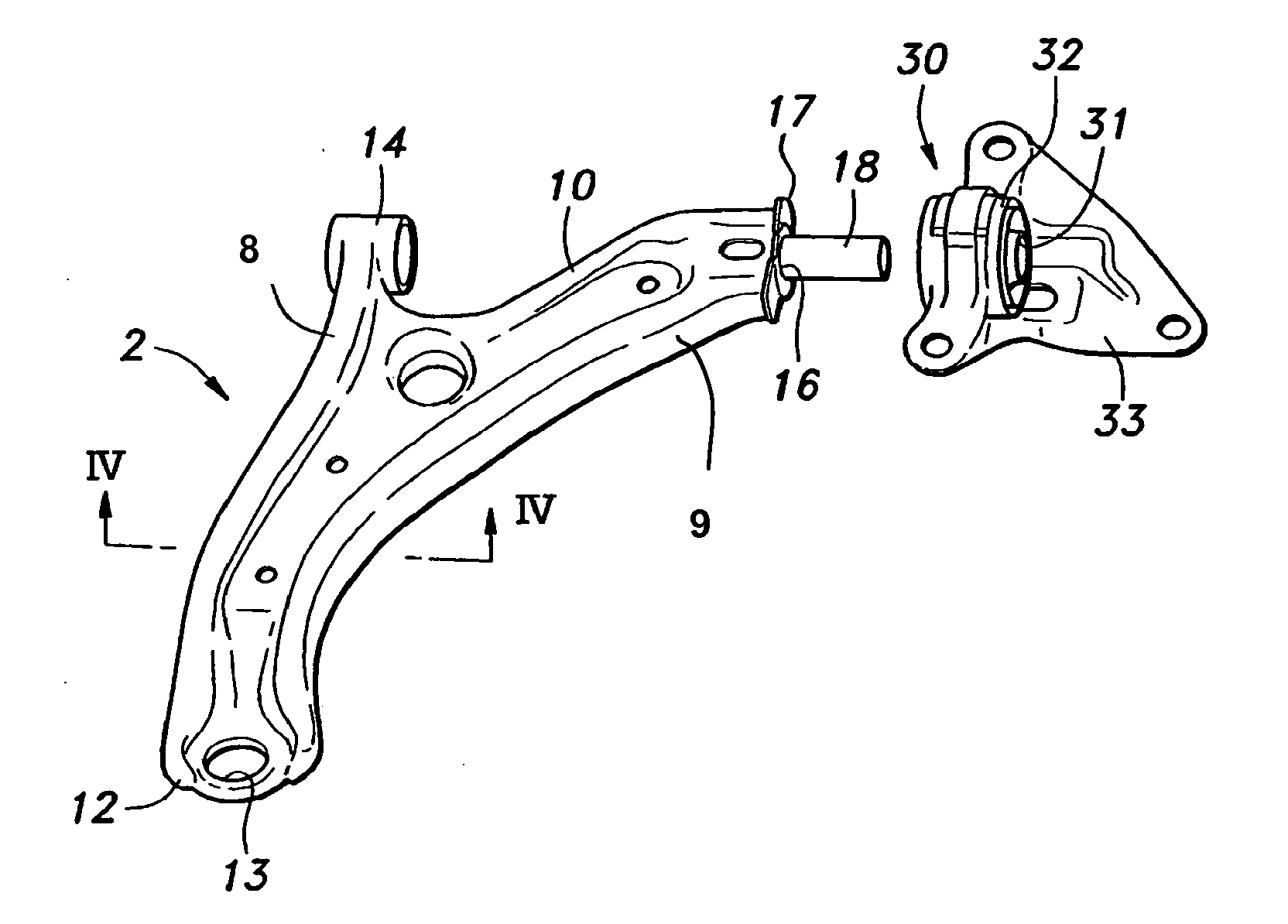
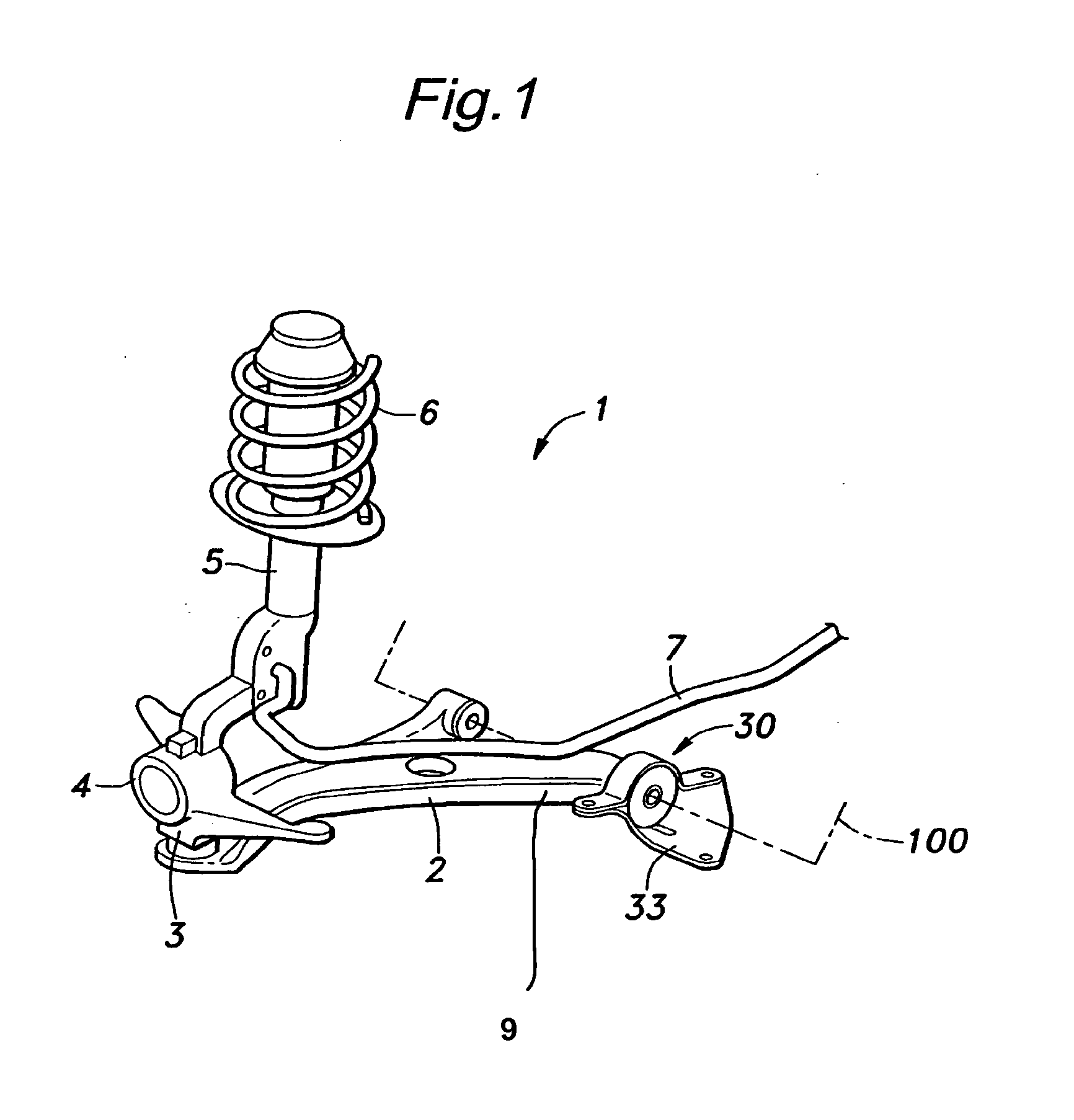
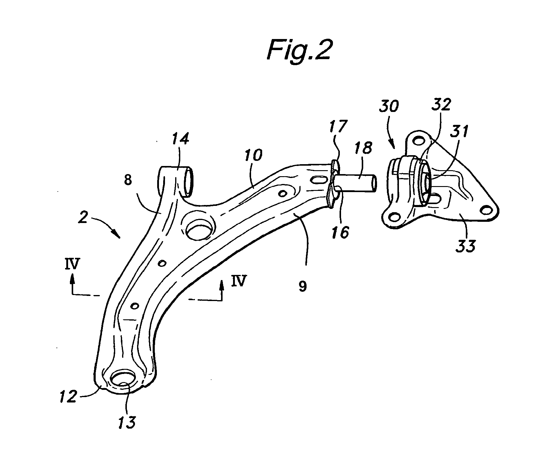
[0025]FIG. 1 shows a strut type vehicle wheel suspension system for a left front wheel using a suspension arm embodying the present invention. This wheel suspension system comprises a lower (suspension) arm 2 having a base end pivotally connected to a vehicle body 100 for a vertical swinging movement, a knuckle 4 pivotally connected to a free end of the lower arm 2 via a ball joint 3, a shock absorber 5 interposed between an upper part of the knuckle 4 and the vehicle body 100, a suspension spring 6 coaxially disposed around the shock absorber 5 and likewise interposed between the knuckle 4 and vehicle body 100, and a stabilizer 7 extending laterally across the vehicle body and having one end connected to the knuckle 4 for the front left wheel and another end connected to the knuckle for the front right wheel not shown in the drawing.

[0026]In this wheel suspension system 1, when an impact from the road surface is applied to the wheel, the knuckle 4 pivotally supported by the lower a...


PUM

PropertyMeasurementUnit
Forceaaaaaaaaaa

Abstract

A suspension arm includes a shaft having a free end extending from an end of the suspension arm and a base end embedded within the said end of the suspension arm, and this shaft is configured to be press fitted into a tubular member of a compliance bush assembly. An opening is formed in the said end of the suspension arm that allows an anvil to be inserted therein to engage the base end of the shaft so that the force of a press fitting process is prevented from affecting the remaining part of the suspension arm. Thus, the press fitting process can be facilitated because very little effort is required to place the suspension arm ready for a press fitting process, and the fixture for holding the suspension arm during a press fitting process can be simplified.

Description

TECHNICAL FIELD[0001]The present invention relates to a suspension arm having a shaft projecting therefrom and a method for press fitting the shaft into a bore of another member such as a tubular member of a compliance bush assembly.BACKGROUND OF THE INVENTION[0002]A vehicle wheel suspension system is interposed between a vehicle body and a corresponding wheel for the purpose of ensuring a favorable ride quality and a motion stability of the vehicle, and typically comprises a suspension arm pivotally attached to the vehicle body for a vertical swinging movement, a knuckle that rotatably supports a wheel and is pivotally connected to a free end of the suspension arm, a coil spring interposed between the knuckle and a suitable part of the vehicle body, and a shock absorber typically coaxially received in the coil spring and interposed between the knuckle and vehicle body.[0003]The suspension arm is typically given with a highly complex shape, and comprises a shaft or pin projecting fr...

Claims


Application Information

Patent Timeline
IPC IPC(8): B60G7/00B23P11/00
CPCB60G7/02B60G2204/1431Y10T29/49945B60G2206/16B60G2206/82092B60G2206/122
Inventor MIYAWAKI, NAOYA
Owner HONDA MOTOR CO LTD
Learn More