Methods and apparatus for suspension lock out and signal generation

a technology of suspension lockout and signal generation, applied in the direction of shock absorbers, cycle equipments, machines/engines, etc., can solve the problems of power loss, high horsepower, and loss usually noticeabl

Active Publication Date: 2010-03-18
FOX FACTORY
View PDF13 Cites 109 Cited by
  • Summary
  • Abstract
  • Description
  • Claims
  • Application Information

AI Technical Summary

Problems solved by technology

There a couple of reasons for that but the result of any bounce is power loss.
Suspension “squat” power loss on motorized vehicles may not be significant because the horsepower available is often more than adequate to compensate for the loss while still providing ample usable power.
In any case that isn't much horsepower and any loss is usually noticeable.
Another power loss mechanism is the force induced bounce that directly results from the rider's interaction with the pedals.
Such heat build up can adversely affect the operation of the suspension damper.
Such changes can affect the damping force generated (and energy dissipation) by the damping piston during operation and may render the damping mechanism ineffective.

Method used


Image

  • Methods and apparatus for suspension lock out and signal generation
  • Methods and apparatus for suspension lock out and signal generation
  • Methods and apparatus for suspension lock out and signal generation

Examples


Embodiment Construction

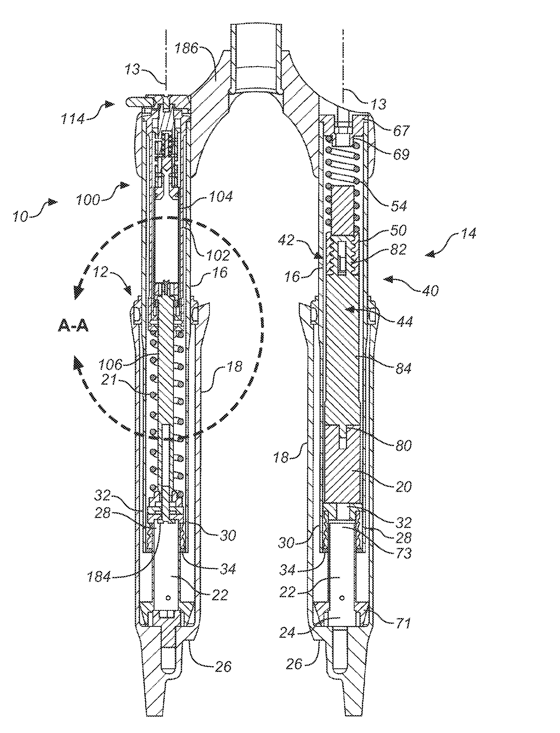
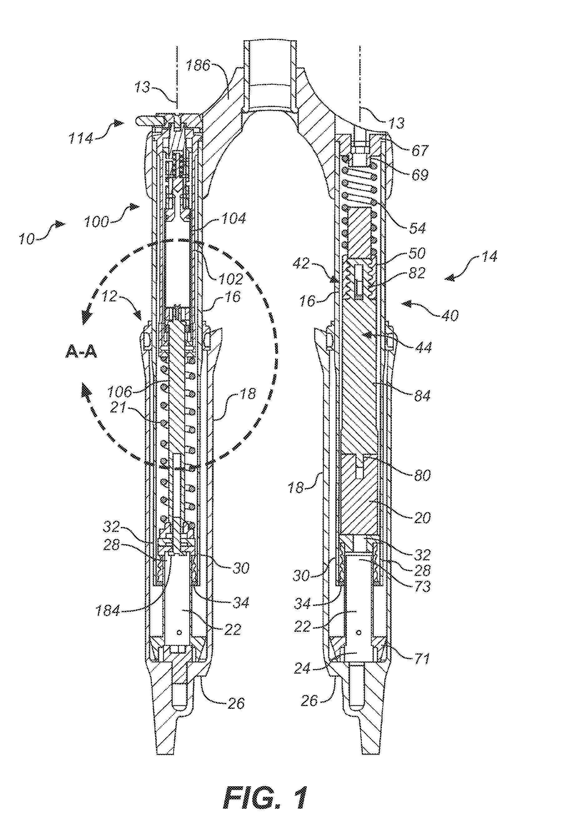
[0018]One embodiment hereof will be described as applied to a bicycle fork. It will be appreciated that such embodiments are equally applicable to rear suspension units or other suspension units that include relatively movable parts that may be selectively immobilized in relation to one another.

[0019]Referring to FIG. 1 of U.S. Pat. No. 6,217,049; shown is a front fork assembly. A modified copy of the FIG. 1 is included as FIG. 1 herein and has been marked with a view A-A. Inner tube 16 is shown telescopically extending within outer tube 18 wherein the tubes 16, 18 have a substantially common longitudinal axis.

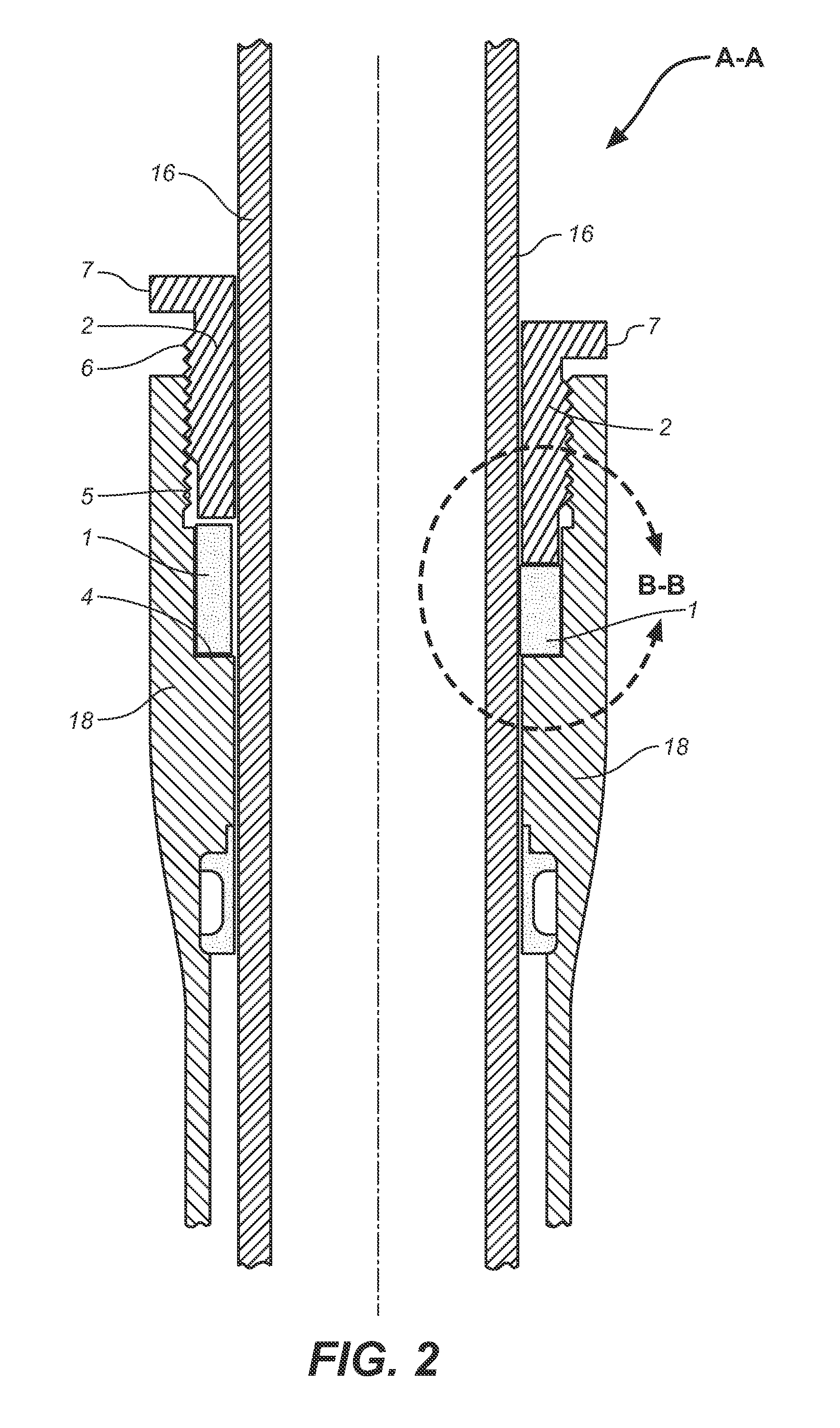
[0020]FIG. 2 shows an embodiment of a mechanical suspension lock schematically depicted within portion A-A as specified in FIG. 1 including tubes 16,18 and wiper (not numbered). FIG. 2 shows an embodiment of a system for immobilizing tube 16 relative to tube 18 thereby allowing for selective creation of a rigid fork comprising tubes 16 and 18. The incidence of other dampening ...


PUM


Abstract

Methods and apparatus for regulating the function of a suspension system are disclosed herein. Suspension characteristics often contribute to the efficiency of a suspended system. Depending on the desired operating parameters of the suspended system, it may be desirable to alter the functional characteristics of the suspension from time to time in order to maintain or increase efficiency. The suspension hereof may be selectively locked into a substantially rigid configuration, and the damping fluid may be phase separated and / or cooled to increase damping rate during use (or offset rate degradation). The suspension hereof may generate power usable to achieve any or all of the foregoing or to be stored for use elsewhere in the suspended system or beyond.

Description

CROSS-REFERENCE TO RELATED APPLICATIONS[0001]This application claims priority to and benefit of U.S. provisional patent application No. 61 / 091,640 filed Aug. 25, 2008, which is incorporated herein, in its entirety, by reference.FIELD OF THE INVENTION[0002]Embodiments of the invention generally relate to methods and apparatus for selectively operating a suspension component. Some embodiments relate to generating a signal and / or current while operating a suspension component.BACKGROUND OF THE INVENTION[0003]Suspension systems and more particularly vehicle and bicycle suspension systems have been available for many years. The predominant form of vehicle suspension, and more specifically, bicycle suspension dampers, are telescopic. Suspension systems typically comprise a spring for energy storage and a damping mechanism for energy dissipation. Suspension systems are used to absorb impact and / or vibration in a wide variety of configurations including vehicle seats, vehicle wheels, indust...

Claims


Application Information

Patent Timeline
Patent Type & Authority Applications(United States)
IPC IPC(8): B60G11/26F16F9/16F16D57/00
CPCB60G2600/72B60G2300/12B60G2500/104B60G2300/60B60G2204/61B60G2204/4604F16F9/06F03G1/00B60G13/14B60G2400/7162H02K7/18B62K25/08F16F9/18F16F9/42
Inventor HAUGEN, DAVID M.
Owner FOX FACTORY
Why Eureka
Try Eureka