Subsea turbine with a peripheral drive

a peripheral drive and subsea turbine technology, applied in the direction of rotors, engine starters, electric generator control, etc., can solve the problems of inefficiency of conventional turbine rotors, water turbines and the methods of using water turbines, and various undesirable limitations,

Inactive Publication Date: 2010-03-18
BEST BRUCE +1
View PDF2 Cites 60 Cited by
  • Summary
  • Abstract
  • Description
  • Claims
  • Application Information

AI Technical Summary

Problems solved by technology

Prior art water turbines and the methods for using water turbines are problematic and suffer from various undesirable limitations.
One such limitation is that water turbines fail to efficiently generate mechanical power from the available power provided by a water flow.
For instance, conventional turbine rotors become inefficient under off-design water flow conditions and, therefore, fail to produce the desired amount of power.
Conventional water turbines, particularly turbine rotors, are also prone to mechanical failures due to harsh and unpredictable environmental conditions.

Method used


Image

  • Subsea turbine with a peripheral drive
  • Subsea turbine with a peripheral drive
  • Subsea turbine with a peripheral drive

Examples


Embodiment Construction

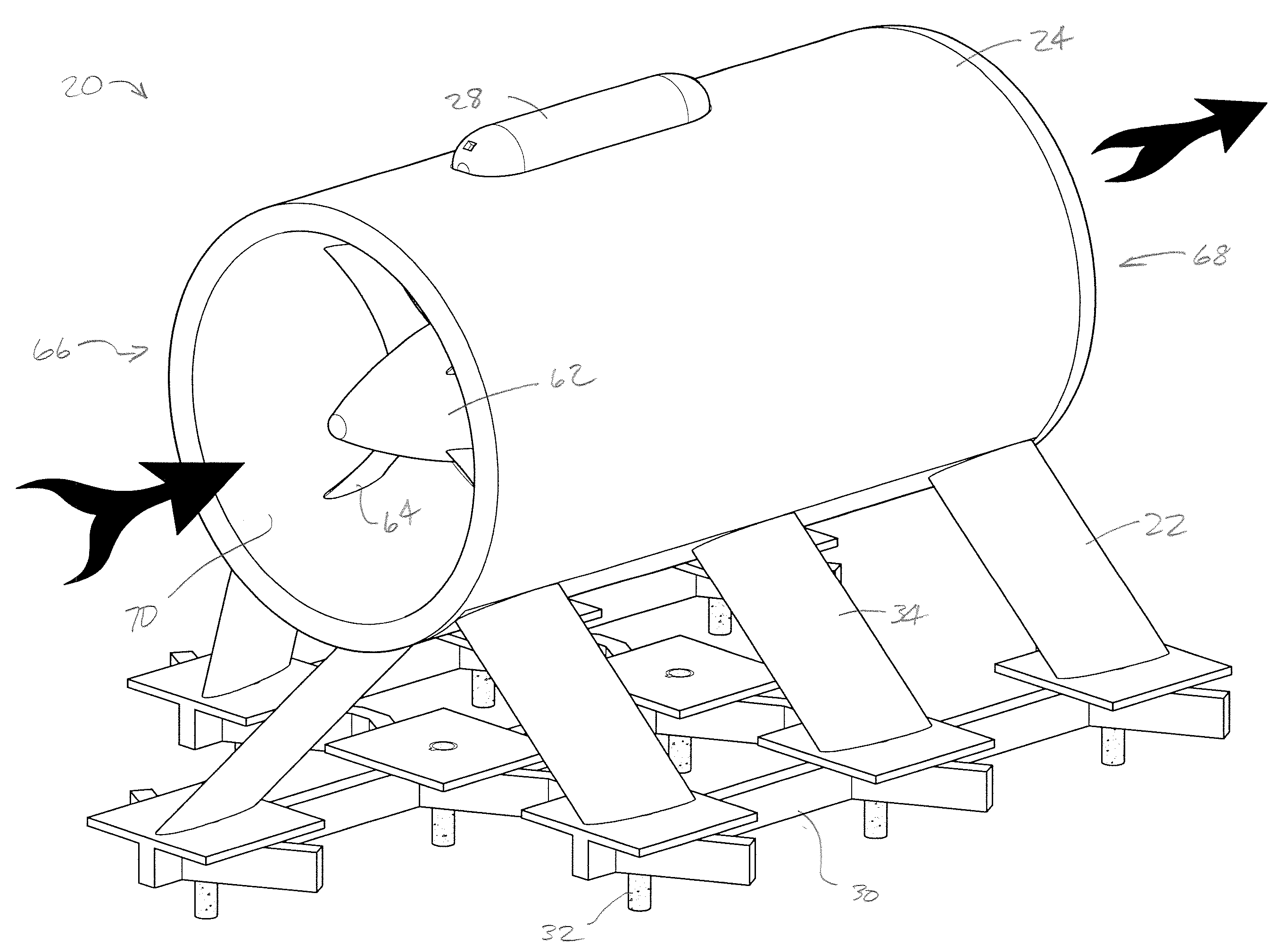
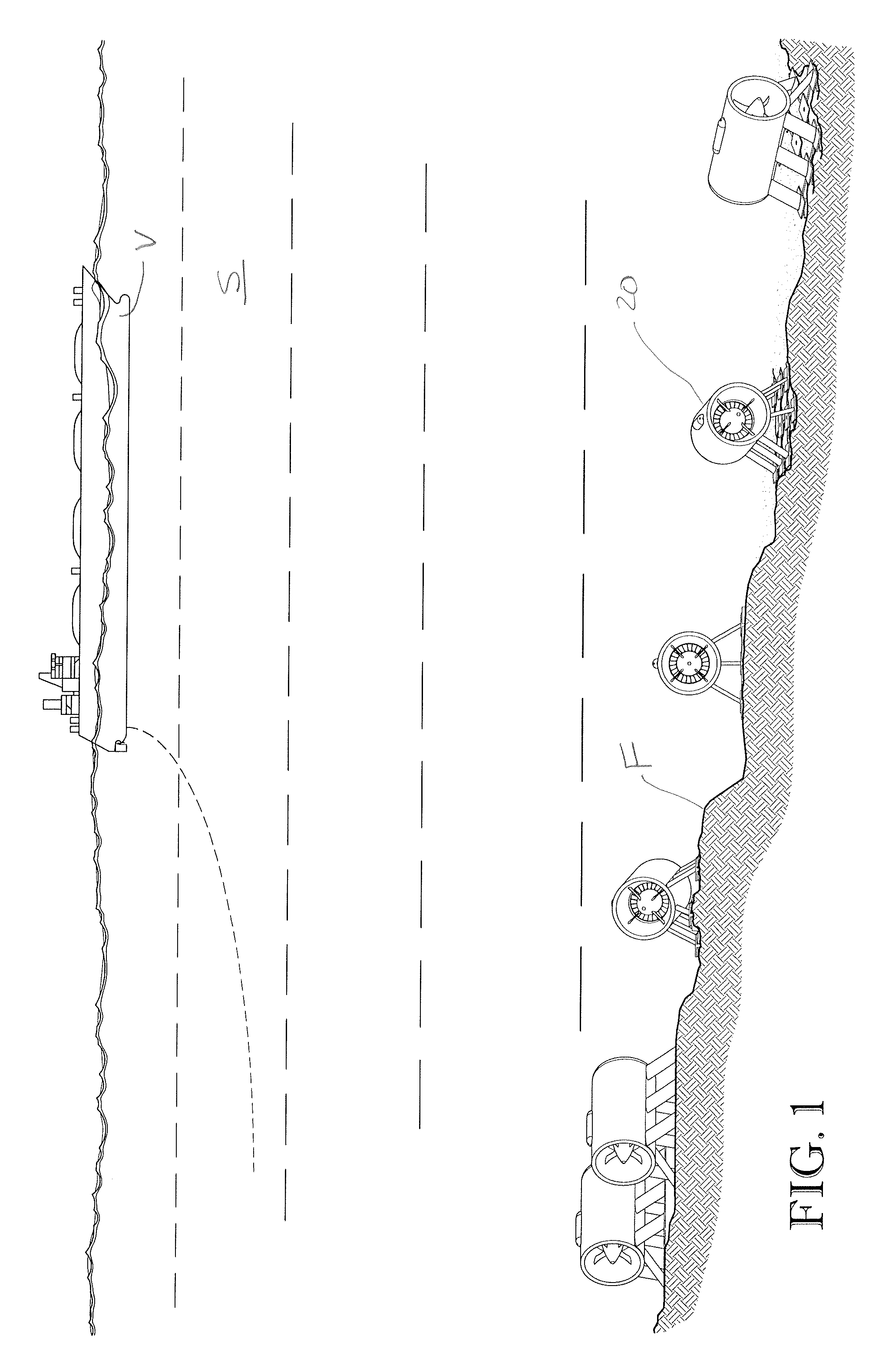
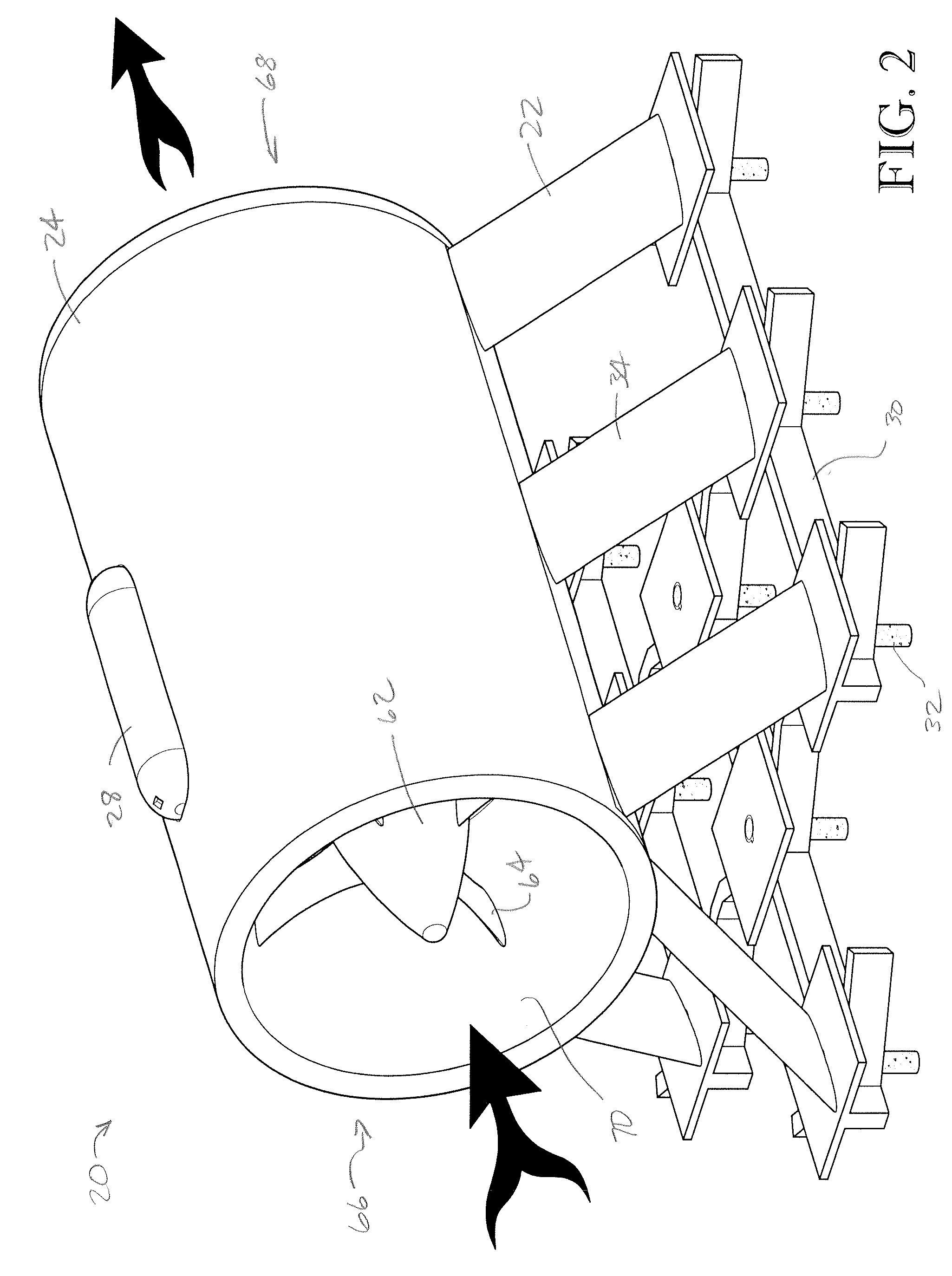
[0028]Turning initially to FIGS. 1-3, a ducted turbine assembly 20 is submerged in sea S and preferably installed on the seafloor F to provide hydroelectric power. The ducted turbine assembly 20 is preferably installed in a location where ocean currents, such as the Gulf Stream, are prevalent, with the assembly 20 being positioned to be powered by a substantially uniform ocean current. The illustrated assembly 20 is preferably secured adjacent to the seafloor F at least about 150 feet below the surface of the sea S to limit interference with shipping vessels V, and can be installed up to about 2,000 feet below the surface to be powered by ocean currents, such as the Gulf Stream. However, the assembly 20 could be installed in other submerged locations or configurations without departing from the scope of the present invention. Ocean currents are a preferred type of water flow for the ducted turbine assembly because ocean currents can be relatively uniform over time and can occur at l...


PUM


Abstract

A ducted water turbine is configured to be installed in a subsea environment to generate hydroelectric power and broadly includes a turbine housing, a turbine rotor, and a generator. The turbine rotor includes a peripheral rim and a plurality of rotor blades mounted to and extending radially inwardly from the rim. The turbine housing includes a duct that permits water to flow through the housing. The peripheral rim is rotatably mounted in the duct, with the water flow causing the turbine rotor to spin. The turbine rotor is drivingly connected to the generator and powers the generator when the turbine rotor is spun by the water flow.

Description

BACKGROUND[0001]1. Field[0002]The present invention relates generally to water turbines. More specifically, embodiments of the present invention concern a ducted water turbine that is submerged in a body of water and is operable to be powered by water flow generated by an ocean current.[0003]2. Discussion of Prior Art[0004]A hydroelectric power facility uses water to generate electric power and normally includes a water turbine to convert water power into mechanical power for turning an electrical generator. Water turbines are often utilized in freshwater dams, but have also been developed for use in open water applications to extract power from naturally-occurring water flows, such as tidal flows or underwater currents.[0005]Prior art water turbines and the methods for using water turbines are problematic and suffer from various undesirable limitations. One such limitation is that water turbines fail to efficiently generate mechanical power from the available power provided by a wa...

Claims


Application Information

Patent Timeline
Patent Type & Authority Applications(United States)
IPC IPC(8): F03B13/10F03B3/06F03B15/04
CPCF03B3/06F03B3/14F03B13/264F05B2240/97F05B2260/74F05B2270/1033Y02E10/20Y02E10/30
Inventor BEST, BRUCEHAUPT, BRIAN
Owner BEST BRUCE
Why Eureka
Try Eureka