
Non resonant inductive power transmission system and method

a non-resonant inductive power and transmission system technology, applied in the direction of transformer/inductance details, circuit arrangements, inductances, etc., can solve the problems of large changes in power transfer, high transmission voltage involved, and difficult maintenan

Active Publication Date: 2010-03-18
POWERMAT TECHNOLOGIES
View PDF99 Cites 129 Cited by
  • Summary
  • Abstract
  • Description
  • Claims
  • Application Information

AI Technical Summary

Benefits of technology

The present invention provides an inductive power transfer system with a primary inductive coil and a secondary inductive coil that can transfer power to an electric load. The system includes a driver that provides an oscillating voltage to the primary coil at a transmission frequency that is different from the resonant frequency of the system. The driver can adjust the transmission frequency based on feedback signals from the secondary coil. The system can regulate power transfer across the inductive coupling based on the feedback signals, which can include the required operating parameters of the electric load. The driver can also include a voltage monitor to detect changes in the primary voltage and a modulator to adjust the transmission frequency. The invention also provides methods for regulating power transfer and monitoring the power received by the load. The technical effects of the invention include improved efficiency and regulation of power transfer for various applications such as charging devices, power tools, and RFID tags.

Problems solved by technology

This can be difficult to maintain as the resonant frequency of the system may fluctuate during power transmission, for example in response to changing environmental conditions or variations in alignment between primary and secondary coils.
At resonance small variations to the system result in large changes to the power transferred.
A further problem associated with resonant transmission is the high transmission voltages involved.

Method used


Image

  • Non resonant inductive power transmission system and method
  • Non resonant inductive power transmission system and method
  • Non resonant inductive power transmission system and method

Examples


Embodiment Construction

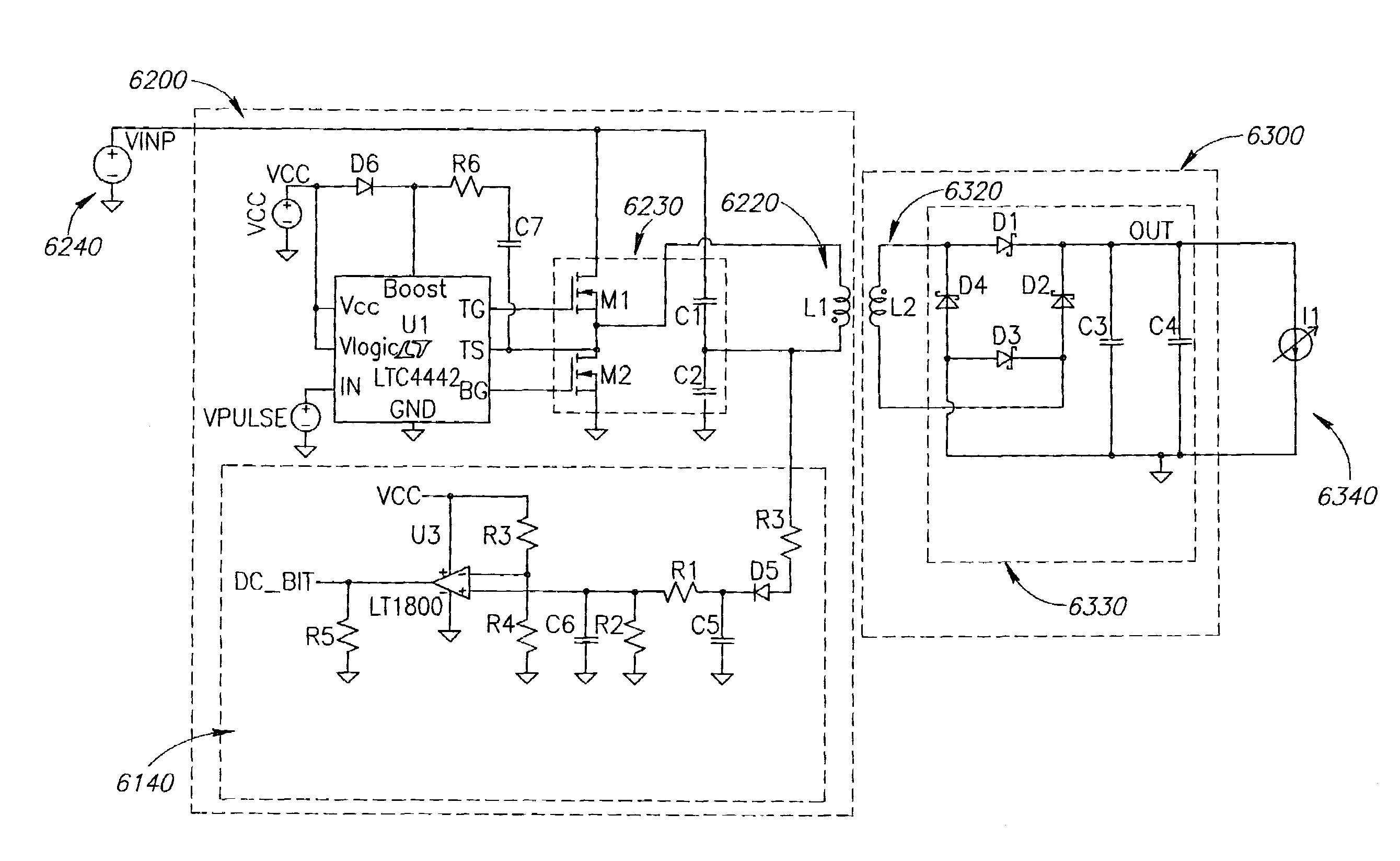
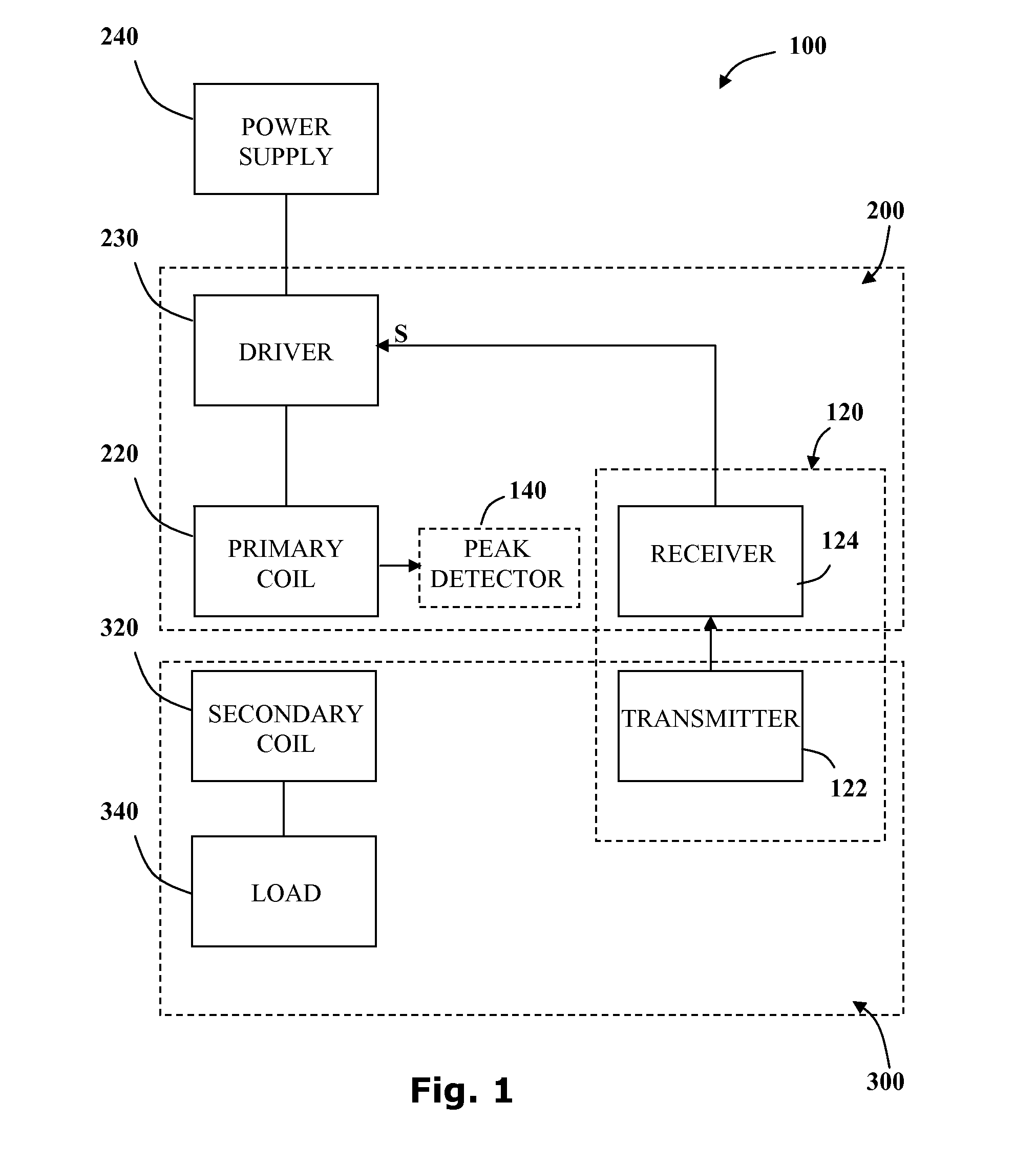
[0033]Reference is now made to FIG. 1 showing a block diagram of the main elements of an inductive power transfer system 100 adapted to transmit power at a non-resonant frequency according to another embodiment of the invention. The inductive power transfer system 100 consists of an inductive power outlet 200 configured to provide power to a remote secondary unit 300. The inductive power outlet 200 includes a primary inductive coil 220 wired to a power source 240 via a driver 230. The driver 230 is configured to provide an oscillating driving voltage to the primary inductive coil 220.

[0034]The secondary unit 300 includes a secondary inductive coil 320, wired to an electric load 340, which is inductively coupled to the primary inductive coil 220. The electric load 340 draws power from the power source 240. A communication channel 120 may be provided between a transmitter 122 associated with the secondary unit 300 and a receiver 124 associated with the inductive power outlet 200. The ...


PUM

PropertyMeasurementUnit
resistanceaaaaaaaaaa
transmission frequencyaaaaaaaaaa

Abstract

Non-resonant inductive power transmission wherein the driving voltage across a primary inductor oscillates at a frequency significantly different from the resonant frequency of the inductive coupling system. Embodiments of the invention include systems and methods for: power regulation using frequency control, fault detection using voltage peak detectors and inductive communication channels.

Description

CROSS-REFERENCE TO RELATED APPLICATIONS[0001]The present invention claims priority of U.S. Provisional Patent Application Ser. No. 61 / 129,526, filed Jul. 2, 2008 and U.S. Provisional Patent Application Ser. No. 61 / 129,859, filed Jul. 24, 2008, both of which are incorporated herein in their entirety.FIELD OF THE INVENTION[0002]The present invention is directed to providing a communications channel for the transfer of feedback signals in inductive power transfer systems. More specifically, the present invention relates to coil-to-coil signal transfer in inductive power couplings.BACKGROUND OF THE INVENTION[0003]Inductive power coupling allows energy to be transferred from a power supply to an electric load without a wired connection therebetween. An oscillating electric potential is applied across a primary inductor. This sets up an oscillating magnetic field in the vicinity of the primary inductor. The oscillating magnetic field may induce a secondary oscillating electrical potential...

Claims


Application Information

Patent Timeline
Patent Type & Authority Applications(United States)
IPC IPC(8): H01F38/00
CPCH01F2038/143H02J5/005Y02B70/1441H02M2007/4815Y02B70/1433H02M3/3376Y02B70/10H02J50/80H02J50/10H02M7/4815H02J50/12
Inventor AZANCOT, YOSSIBEN-SHALOM, AMIRGREENWALD, OOLAROFE, ARIKLEIBOVITZ, ALFREDASHERY, MOTI
Owner POWERMAT TECHNOLOGIES
Learn More