Antenna device and electronic apparatus using the same

a technology of electronic equipment and antenna device, applied in the structure of radiating elements, elongated active element feed, resonance antenna, etc., can solve the problems of deteriorating reception quality, reducing radiation resistance, and isolating between antenna conductors, so as to improve the reception quality of the first antenna device, reduce radiation resistance, and improve the effect of loss resistan

Inactive Publication Date: 2010-03-18
PANASONIC CORP
View PDF8 Cites 12 Cited by
  • Summary
  • Abstract
  • Description
  • Claims
  • Application Information

AI Technical Summary

Benefits of technology

[0006]The present invention improves reception quality in an electronic apparatus including plural antenna devices.
[0008]In the conductor composed of the second and third antenna conductors in the above-described first antenna device, (m+1)λ / 2 resonance in the second frequency band occurs. For this reason, the resonance current hardly flows through the ground organizer, and most of the current is distributed only to the second and third antenna conductors. At this moment, downsizing these antenna conductors in such as a meander shape decreases the radiation resistance at the antenna conductor, and thus the influence by the loss resistance increases. Consequently, in the first antenna device, the received power in the second frequency band (i.e. a disturbing wave band) can be attenuated, thereby improving the reception quality of the first antenna device.

Problems solved by technology

This causes isolation between antenna conductors 5, 6 to decrease, undesirably deteriorating reception quality.[Patent literature 1] Japanese Patent Unexamined Publication No.

Method used


Image

  • Antenna device and electronic apparatus using the same
  • Antenna device and electronic apparatus using the same
  • Antenna device and electronic apparatus using the same

Examples


first exemplary embodiment

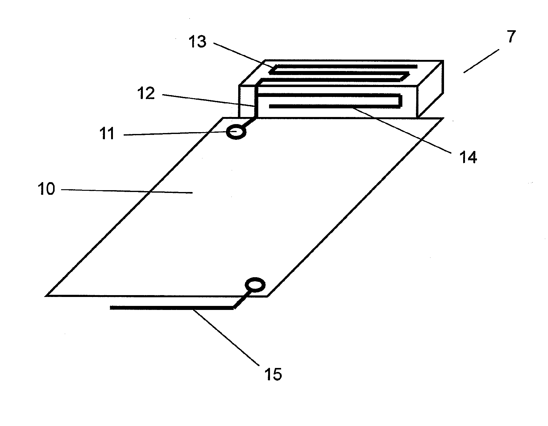
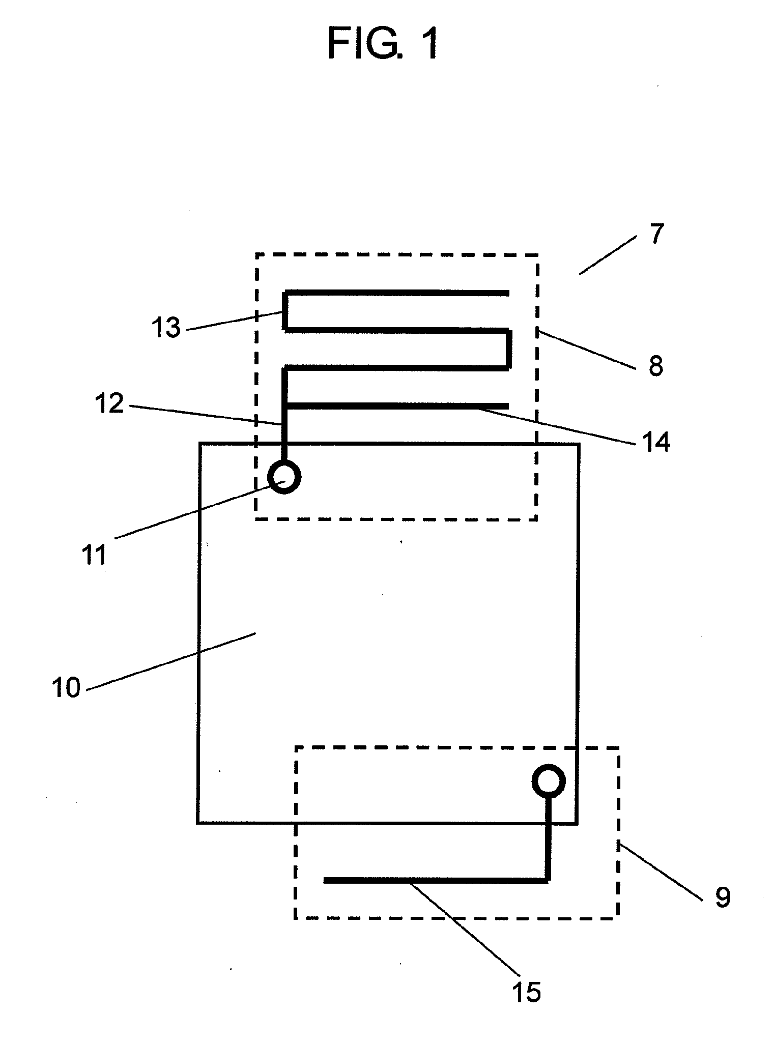
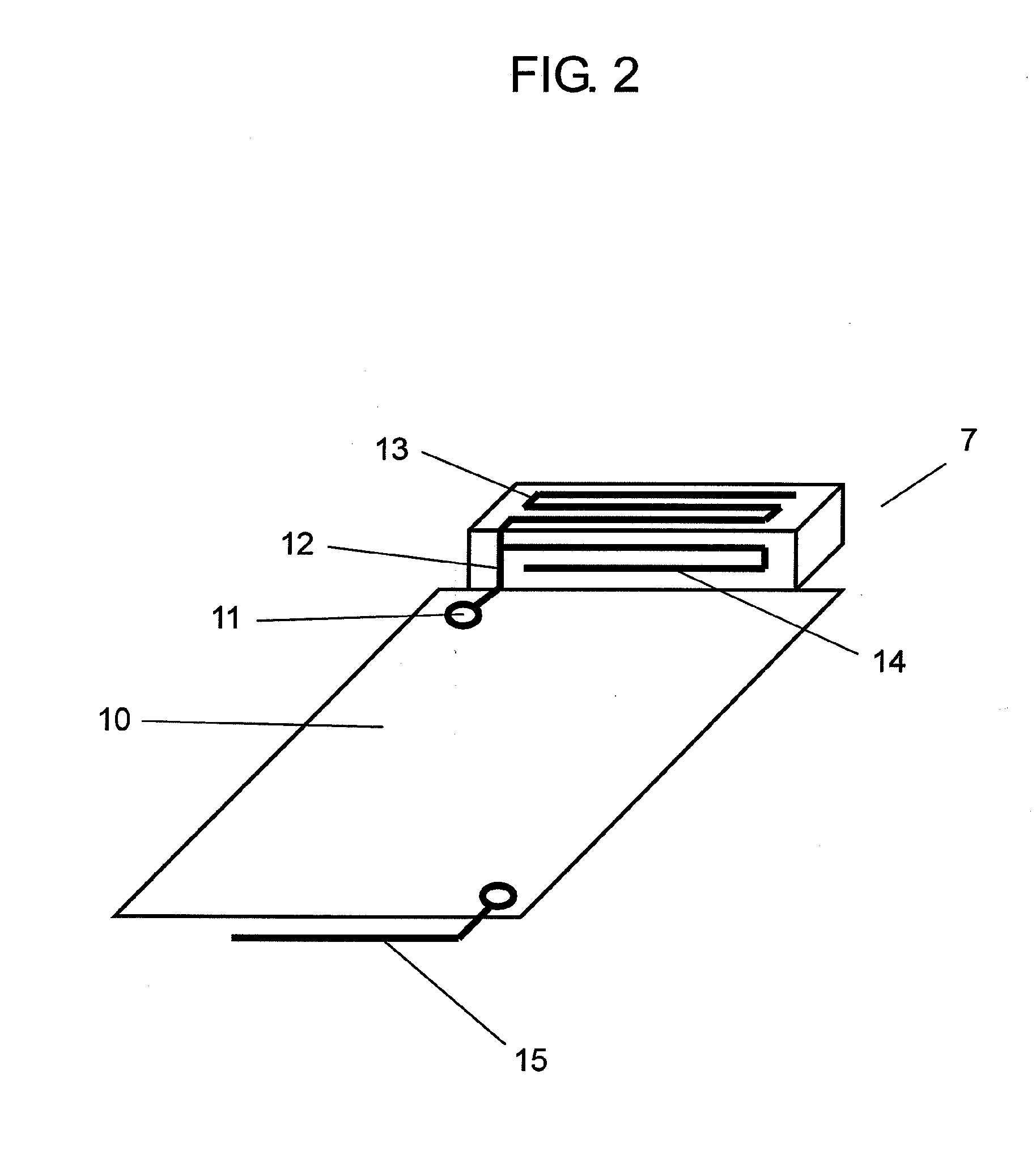
[0039]Hereinafter, a description is made of the first exemplary embodiment of the present invention using some related drawings. FIG. 1 is a schematic diagram of an electronic apparatus according to the first embodiment. FIG. 2 is a perspective view of the electronic apparatus according to the first embodiment. In FIG. 1, electronic apparatus 7 includes first antenna device 8, which is a first communication unit communicating using a first frequency band; and second antenna device 9, which is a second communication unit communicating using a second frequency band different from the first one.

[0040]First antenna device 8 includes ground organizer 10; feeding unit 11 placed on ground organizer 10; first antenna conductor 12 with its one end connected to feeding unit 11; and second antenna conductor 13 and third antenna conductor 14 both branch connected to the other end of first antenna conductor 12. The sum of the length of first antenna conductor 12 and that of second antenna conduc...


PUM


Abstract

The present invention improves reception quality in an electronic apparatus including plural antenna devices. For this purpose, first antenna device (8) of electronic apparatus (7) according to the present invention includes ground organizer (10); feeding unit (11) placed on ground organizer (10); first antenna conductor (12) with its one end connected to feeding unit (11); and second antenna conductor (13) and third antenna conductor (14) both branch connected to the other end of first antenna conductor (12). The sum of the length of first antenna conductor (12) and that of second antenna conductor (13) is substantially (¼+n / 2) times the wavelength of a signal in the first frequency band, and additionally the sum of the length of second antenna conductor (13) and that of third antenna conductor (14) is substantially (½+m / 2) times the wavelength of a signal in the second frequency band.

Description

TECHNICAL FIELD[0001]The present invention relates to an antenna device and an electronic apparatus using the same.BACKGROUND ART[0002]Hereinafter, a description is made of an electronic apparatus such as a conventional mobile communication terminal using FIG. 17. In FIG. 17, conventional electronic apparatus 1 includes first antenna device 2 communicating using a first frequency band; and second antenna device 3 communicating using a second frequency band different from the first one. First antenna device 2 and second antenna device 3 are formed on ground organizer 4 and include antenna conductors 5, 6 with each length substantially ¼ times the wavelength of a signal in each frequency band, on each antenna conductor.[0003]There is patent literature 1, for example, known as document information on prior art related to this invention.[0004]However, electronic apparatus 1 has been downsized in recent years; first antenna device 2 and second antenna device 3 are positioned extremely cl...

Claims


Application Information

Patent Timeline
Patent Type & Authority Applications(United States)
IPC IPC(8): H01Q1/24H01Q1/38H01Q1/52H01Q5/10H01Q9/42H01Q21/30H04B1/3822H04B1/40
CPCH01Q1/243H01Q5/371H01Q9/42H01Q1/38
Inventor OKAYAMA, MOTOYUKIOZAKI, AKIHIRO
Owner PANASONIC CORP
Why Eureka
Try Eureka