Video camera perspective calculation

Inactive Publication Date: 2010-03-18
MARCH NETWORKS
View PDF7 Cites 21 Cited by
  • Summary
  • Abstract
  • Description
  • Claims
  • Application Information

AI Technical Summary

Benefits of technology

[0008]It is an object of the present invention to obviate or mitigate at least one disadvantage of previous manual video camera configuration approaches.
[0014]The video camera perspective calculator can further include a data enhancer, in communication with the automatic plane calculator, to iteratively eliminate outliers from data samples to be processed by the automatic plane calculator.

Problems solved by technology

The calibration is susceptible to user error that can be introduced by incorrectly drawing the boxes, or providing inaccurate distances corresponding with the boxes.
The manual setup described above can be very time consuming, especially in cases where there are many cameras to be set up in a network.

Method used


Image

  • Video camera perspective calculation
  • Video camera perspective calculation
  • Video camera perspective calculation

Examples


Embodiment Construction

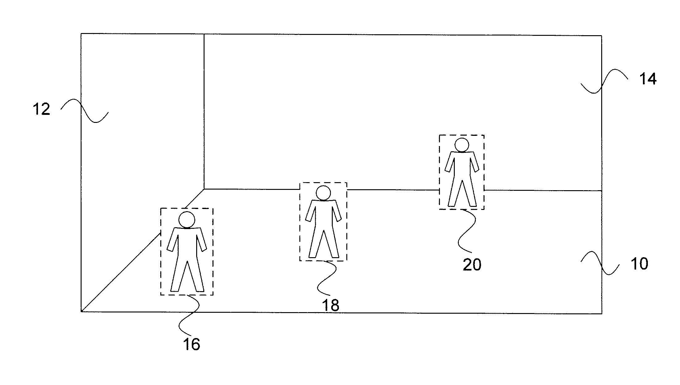
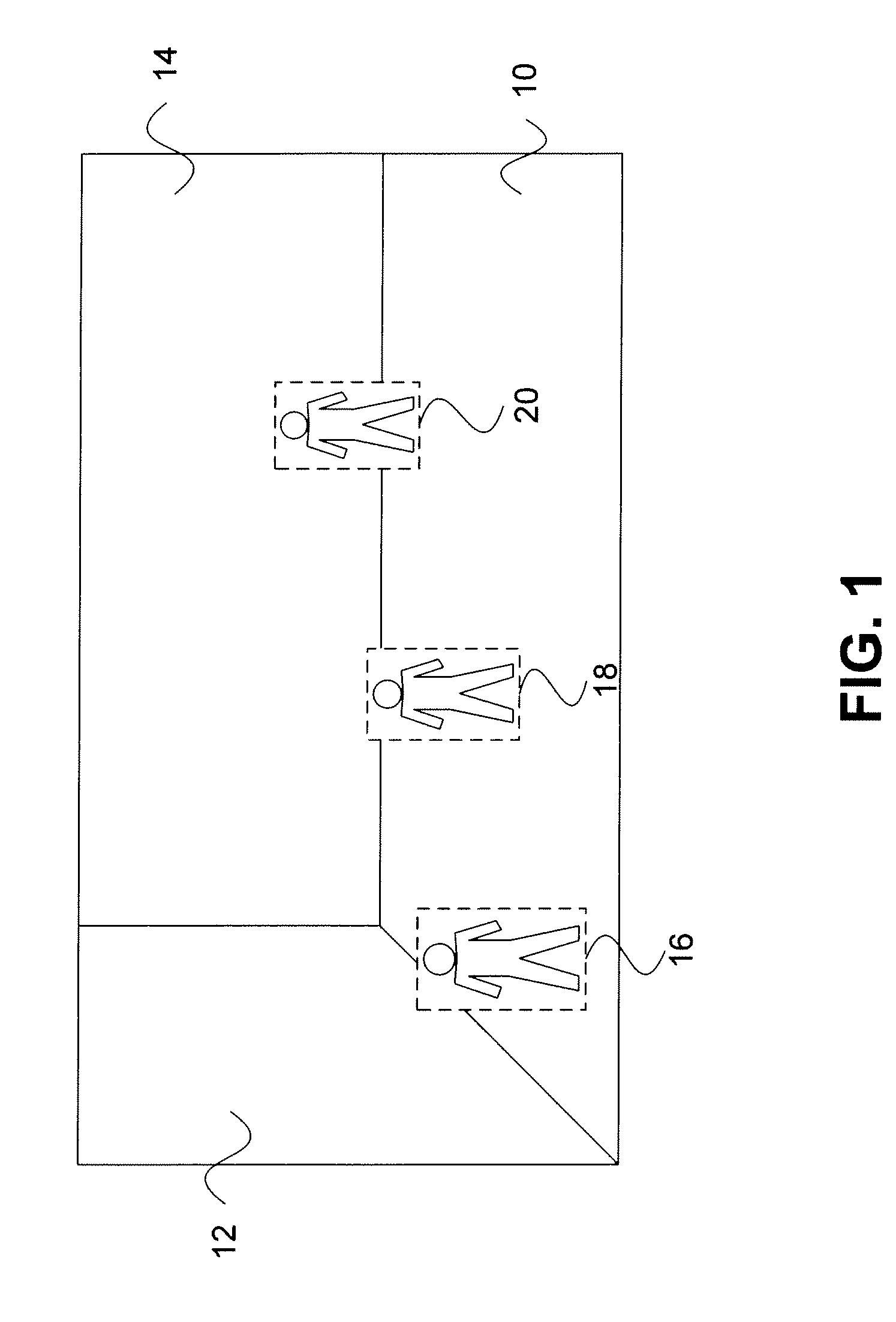
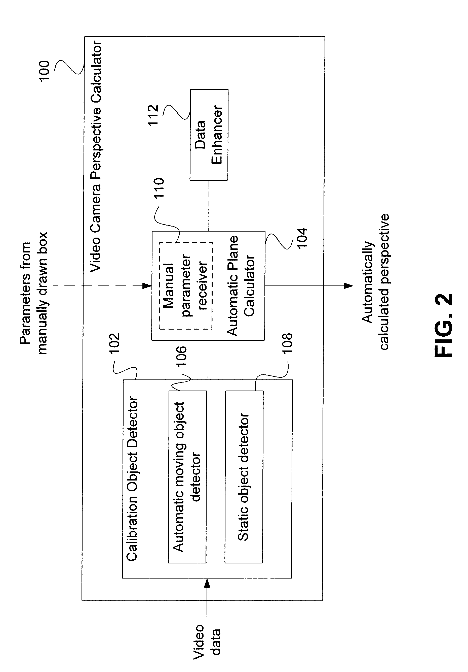
[0029]Generally, the present invention provides a method and system for automatic calibration of a video camera by providing automatic perspective calculation. A calibration object detector is arranged to detect a calibration object in video data representing a scene observed by a video camera, and arranged to gather object data for the detected calibration object at a multiplicity of positions, such as three or more positions. The calibration object detector can include an automatic moving object detector and / or a static object detector. An automatic plane calculator is in communication with the calibration object detector and arranged to calculate the perspective of the camera based on gathered object data for at least one calibration object at a multiplicity of positions. The automation provided can enhance the operation of video analytics systems and reduce errors that can be introduced when an unskilled operator manually enters parameters on which the perspective is estimated.

[...


PUM


Abstract

A method and system are provided for automatic calibration of a video camera by providing automatic perspective calculation. A calibration object detector is arranged to detect a calibration object in video data representing a scene observed by a video camera, and arranged to gather object data for the detected calibration object at a multiplicity of positions, such as three or more positions. The calibration object detector can include an automatic moving object detector and / or a static object detector. An automatic plane calculator is in communication with the calibration object detector and arranged to calculate the perspective of the camera based on gathered object data for at least one calibration object at a multiplicity of positions. The automation provided can enhance the operation of video analytics systems and reduce errors that can be introduced when an unskilled operator manually enters parameters on which the perspective is estimated.

Description

FIELD OF THE INVENTION[0001]The present invention relates generally to video surveillance. More particularly, the present invention relates to the estimation or calculation of a perspective of a video camera.BACKGROUND OF THE INVENTION[0002]Video surveillance systems are used to keep watch over physical areas to assist in identifying events of interest. Such events, and associated data, can relate to maintaining safety and security, mitigating risk, increasing operational efficiency, preventing loss of products or revenue, gathering business intelligence, and a variety of other applications.[0003]FIG. 1 illustrates a typical scene observed by a video surveillance camera. This exemplary scene shows a room or area having a floor 10 and two walls 12 and 14. Using known approaches for setting up or calibrating a camera, it is necessary for an operator to manually provide an observed size of a typical person appearing at a minimum of three different distances observable in the scene. The...

Claims


Application Information

Patent Timeline
IPC IPC(8): H04N7/18
CPCH04N17/002
Inventor DISARO, MAUROMONICA, FRANCESCO
Owner MARCH NETWORKS
Why Eureka
Try Eureka