Object lens driving apparatus and manufacturing method thereof

Active Publication Date: 2010-03-18
MITSUBISHI ELECTRIC CORP
View PDF3 Cites 6 Cited by
  • Summary
  • Abstract
  • Description
  • Claims
  • Application Information

AI Technical Summary

Benefits of technology

[0010]According to the present invention, after the objective lens is bonded using the first bonding adhesive, adjustment of the optical axis of the objective lens is performed utilizing a deformation of the first bonding adhesive, and then the objective lens

Problems solved by technology

However, as a numerical aperture (NA) of the objective lens increase owing to a density growth of the optica

Method used


Image

  • Object lens driving apparatus and manufacturing method thereof
  • Object lens driving apparatus and manufacturing method thereof
  • Object lens driving apparatus and manufacturing method thereof

Examples


Example

Embodiment 1

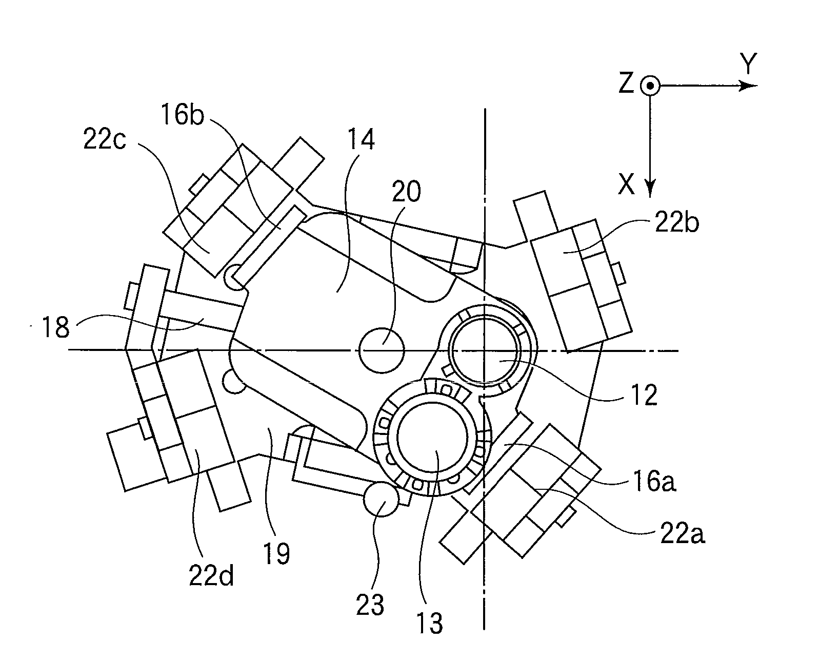
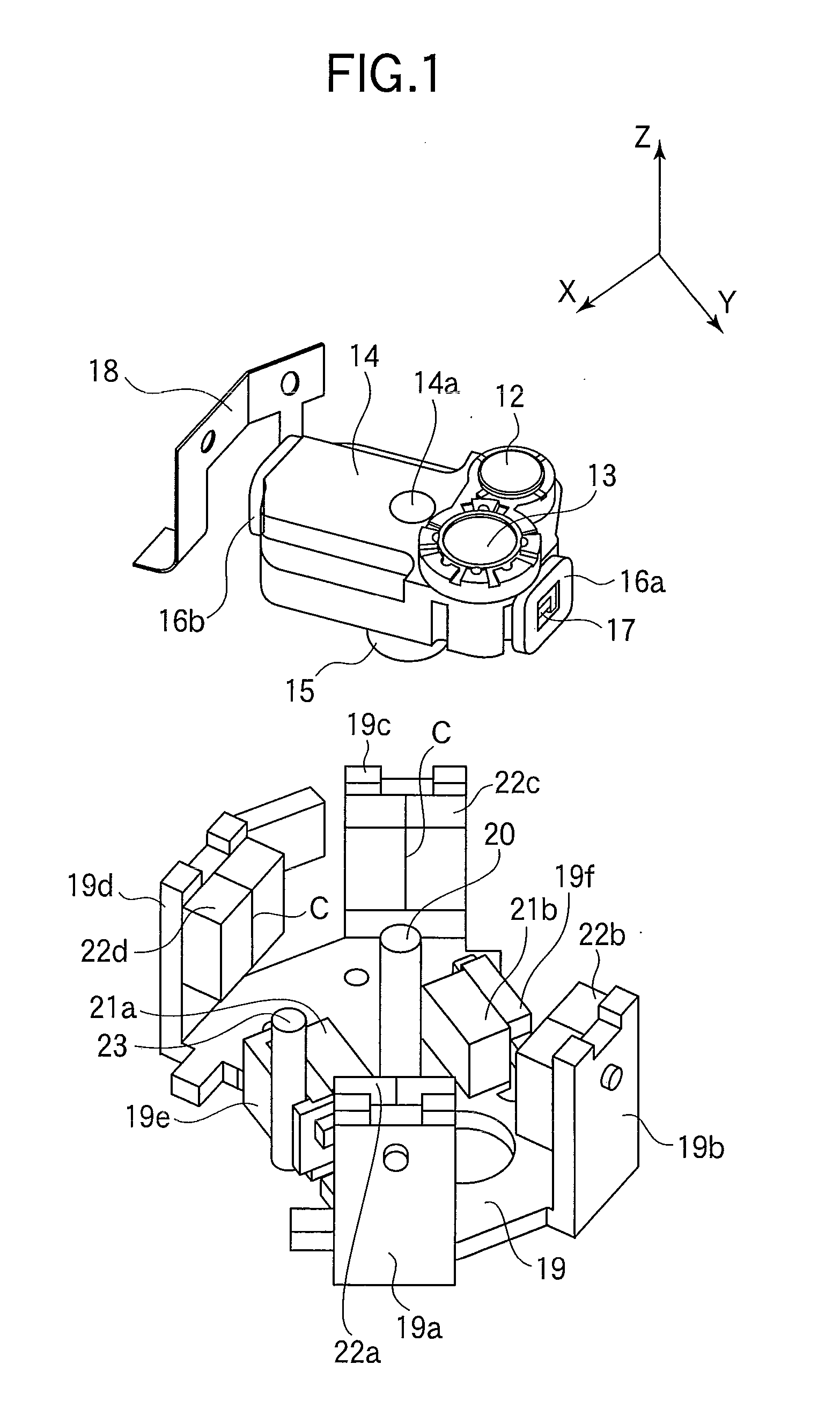
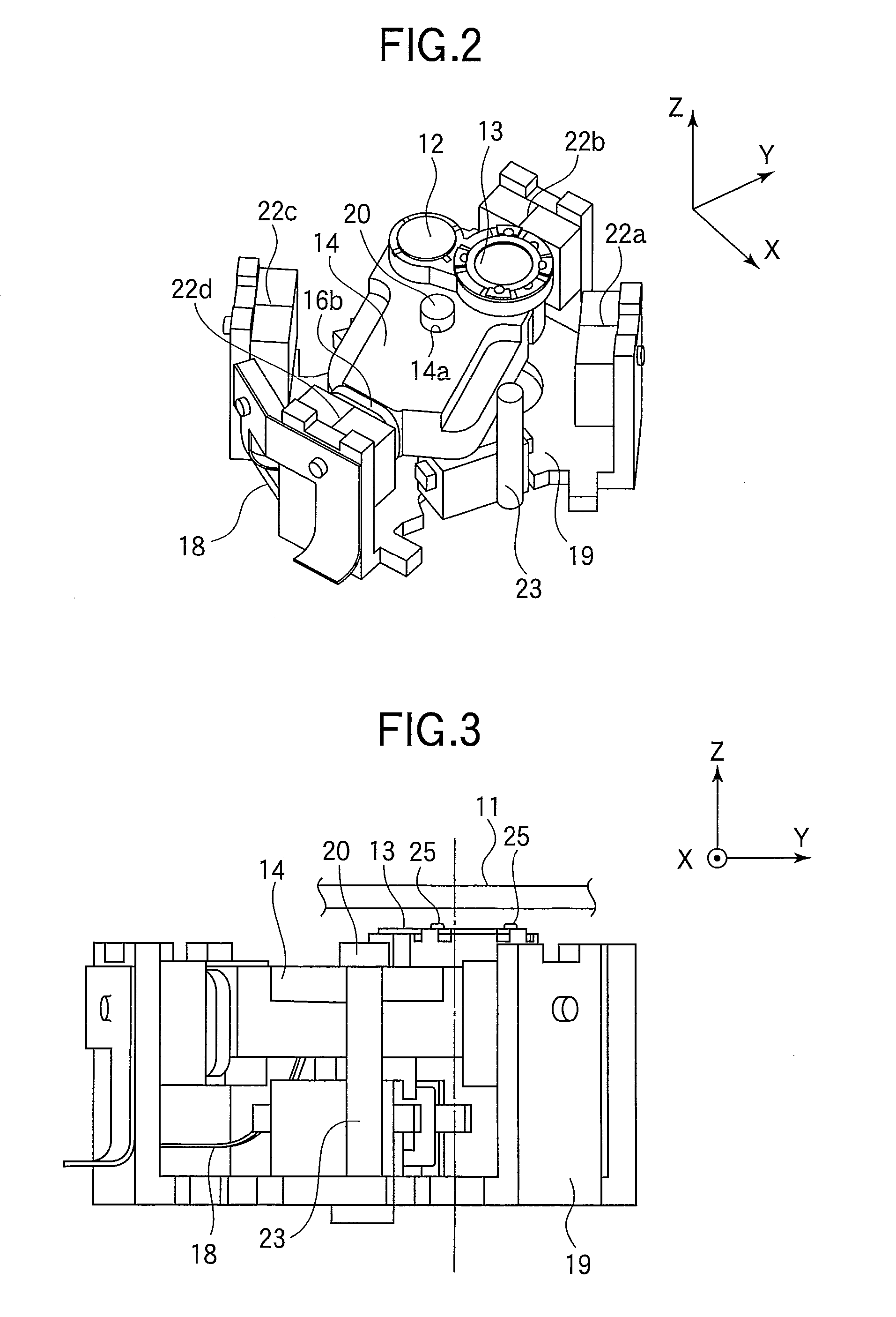
[0036]FIG. 1 is an exploded perspective view showing an objective lens driving apparatus according to Embodiment 1 of the present invention divided into a movable part and a stationary part. FIG. 2 is a perspective view showing the objective lens driving apparatus in which the movable part and the stationary part shown in FIG. 1 are assembled. FIG. 3 is a side view showing the objective lens driving apparatus of FIG. 2. FIG. 4 is a plan view showing the objective lens driving apparatus shown in FIG. 2 in a state where a first objective lens is selected. FIG. 5 is a plan view showing the objective lens driving apparatus shown in FIG. 2 in a state where a second objective lens is selected.

[0037]Here, a direction perpendicular to a recording surface of an optical disk is defined as Z direction. Along the direction, a direction from an objective lens toward the optical disk is defined as +Z direction (upward), and its opposite direction is defined as −Z direction (downward)....

Example

Embodiment 2

[0085]In the above described Embodiment 1, explanation has been given of the objective lens driving apparatus of a rotary-type in which the light flux emitted from the blue semiconductor laser and the light flux emitted from the dual-wavelength semiconductor layer pass through the common light path, and the objective lenses are switched according to the optical disk 11 to be used. In contrast, this Embodiment 2 relates to an objective lens driving apparatus of a wire-supported type in which a light flux emitted from a blue semiconductor laser and a light flux emitted from a dual-wavelength semiconductor laser proceed along different light paths and respectively pass through the first objective lens 12 and the second objective lens (i.e., the switching of the objective lenses by the rotation of the lens holder is not performed).

[0086]FIG. 18 is an exploded perspective view showing an objective lens driving apparatus according to Embodiment 2 of the present invention. FIG....


PUM

PropertyMeasurementUnit
Modulusaaaaaaaaaa
Lightaaaaaaaaaa
Optical propertiesaaaaaaaaaa

Abstract

An objective lens driving apparatus includes an objective lens (13) collecting a light flux emitted from a light source on a optical disk (11), and a lens holder (14) holding the objective lens (13). The lens holder (14) includes a first bonding portion (14i) and a second bonding portion (14j) for holding the objective lens (13) by means of bonding. The objective lens (13) is fixed to the lens holder (14) by applying a first bonding adhesive (25) to the first bonding portion (14i) to thereby bond the objective lens (13) thereto, adjusting an inclination of an optical axis of the objective lens (13) while causing the first bonding adhesive (25) to deform, and applying a second bonding adhesive (26) to the second bonding portion (14j). The second bonding adhesive (26) has a larger Young's modulus after curing than the first bonding adhesive (25).

Description

TECHNICAL FIELD[0001]The present invention relates to objective lens driving apparatuses that perform recording and / or reproducing of information with respect to information recording media, and particularly relates to configurations for adjusting inclinations of optical axes of objective lenses.BACKGROUND ART[0002]Recently, there have been developed a variety of optical disks having different recording densities and thicknesses. Recording and reproducing of information are performed using lights of wavelengths corresponding, to specifications of respective optical disks. For example, there are a CD (Compact Disc) whose usable wavelength is in the vicinity of 780 nm, a DVD (Digital Versatile Disc) whose usable wavelength is in the vicinity of 660 nm, and a BD (Blu-Ray Disc) and a HD-DVD (High Definition DVD) whose usable wavelength is in the vicinity of 405 nm. An objective lens driving apparatus which is compatible with a plurality of kinds of optical disks with different usable wa...

Claims


Application Information

Patent Timeline
IPC IPC(8): G11B7/00B29C65/00G11B7/135
CPCG11B7/0935G11B2007/0006G11B7/22G11B7/1374
Inventor YABE, MITORUNAKAMURA, KEIJI
Owner MITSUBISHI ELECTRIC CORP
Why Eureka
Try Eureka